Continuous die mould of part

A technology for parts and molds, which is applied to the field of continuous punching and dies for electrical components, can solve the problems of inability to work continuously and the working efficiency of punching dies is low, and achieve the effects of low manufacturing cost, simple structure and improved working efficiency.

Inactive Publication Date: 2010-11-03
昆山凯意工模具配套有限公司
View PDF5 Cites 5 Cited by
  • Summary
  • Abstract
  • Description
  • Claims
  • Application Information

AI Technical Summary

Problems solved by technology

[0006] The purpose of the present invention is to overcome the disadvantages of the prior art that the mold head needs to be replaced and cannot work continuously, resulting in low working efficiency of the punching die, and to provide a punching die with safe operation and no need to replace the die head for one-time molding

Method used


Image

  • Continuous die mould of part
  • Continuous die mould of part
  • Continuous die mould of part

Examples


Embodiment Construction

[0015] In order to make the technical means, creative features, goals and effects achieved by the present invention easy to understand, the present invention will be further described below in conjunction with specific illustrations.

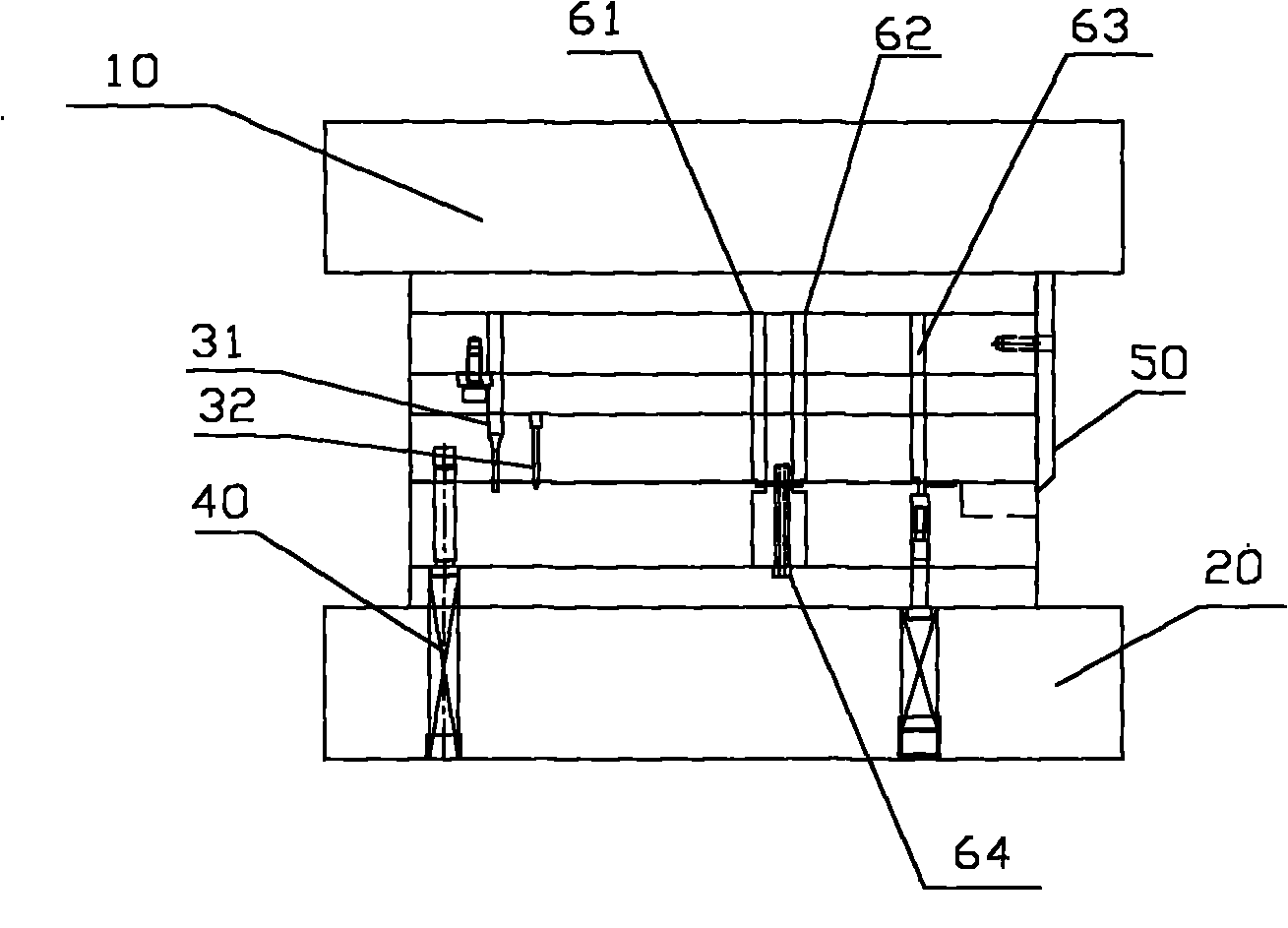
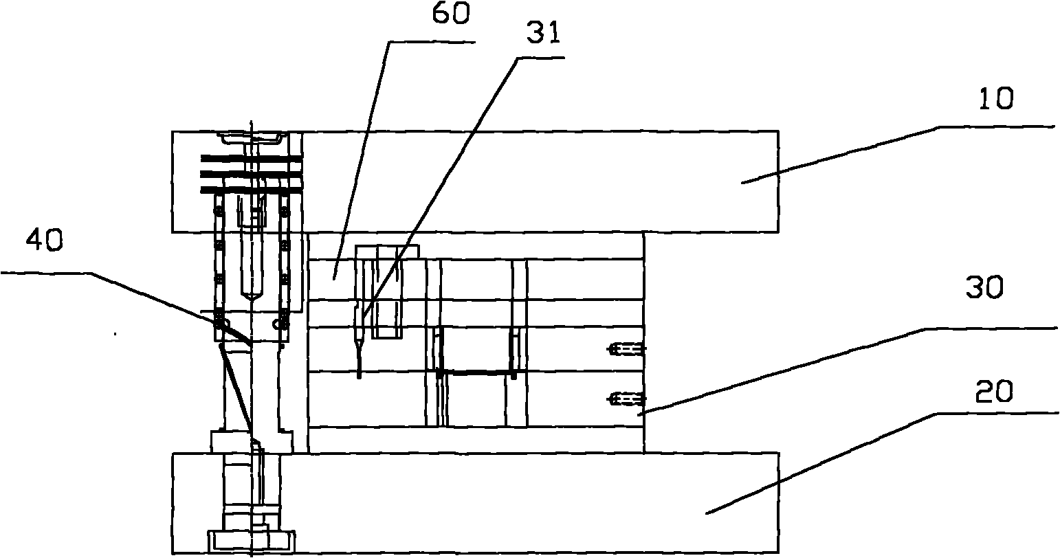
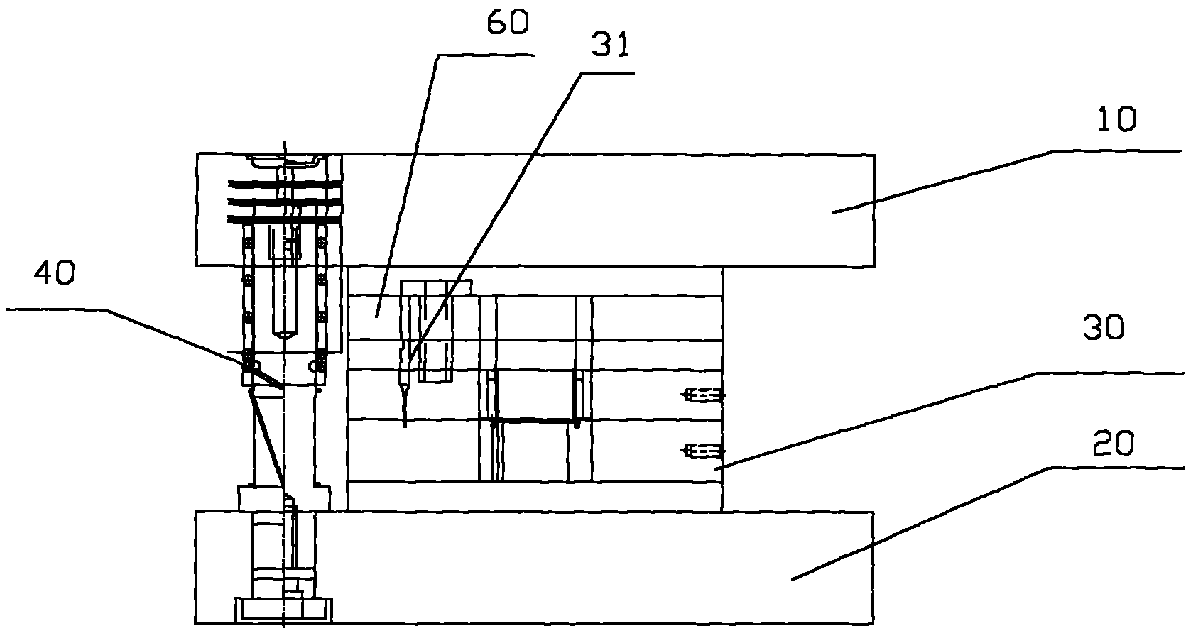
[0016] refer to figure 1 And shown in Fig. 3: parts continuous stamping die mold, this mold comprises upper die holder 10, lower die holder 20, punch, die, is installed in lower die holder 20 backing plate 30, strip and cutting knife 40; The upper mold holder is equipped with an upper mold fixing plate 60, and the punch mold is also composed of the first guide punch 31 and the second guide punch 32 for controlling the PIN distance and guiding, the floating dual-purpose tip 40, the forming insert 64 and the punch 61, 62, 63, the punch includes a first punch 61, a second punch 62 and a third punch 63; the floating dual-purpose pin 40 is set on the lower mold base 20, and one side is provided with a forming insert 64; the material strip is set abo...


PUM


Abstract

The invention discloses a continuous die mould of a part, comprising an upper die holder, a lower die holder, a terrace die, a die, a punch fixed plate, an upper base plate, a material belt and a cutter. a terrace die and a die in each station are sequentially arranged on the terrace die and the die of the mould in the punch process order of the electrical parts; a guide pin for controlling the PIN distance and for guiding is further fixed on the central position of the upper base plate; the guide pin comprises a first guide punch and a second guide punch; both the first and second guide punches are fixedly arranged on the upper die holder; the mould is further provided with a pin with double purposes of floatation and opening, a molded insert core and a punch. The invention is featured by convenient manufacturing, low cost, safety, stability, rapid lead time and low manufacturing cost, can satisfy a certain processing quality requirement, ensures that the punching operation of mould in multiple steps is finished continuously, and obviously improving the working efficiency, thereby providing an economic and effective way for trail production of new products and production of stamping parts without high batch requirement.

Description

Technical field: [0001] The invention relates to a punching die, in particular to a continuous punching die for electrical components that saves processes. Background technique: [0002] In die stamping technology, the final completion of stamping products often requires multiple processes to achieve. Usually, for each stamping process, the stamping head needs to be removed from the punching machine and replaced with a stamping die for a new process. head. When the product requires multiple stamping processes, the work of replacing the die head is very cumbersome, and the operation of the lathe must be stopped from time to time, which is time-consuming and unsafe. Later, the continuous mold of punch press appeared, mainly relying on the continuous mechanism of mold design, but the mold mechanism is too complicated and cumbersome. [0003] The mold used for stamping is called stamping die, or punching die for short. Die is a special tool for mass processing materials (meta...

Claims


Application Information

Patent Timeline
Patent Type & Authority Applications(China)
IPC IPC(8): B21D37/10B21D35/00
Inventor 孙新良
Owner 昆山凯意工模具配套有限公司
Why Eureka
Try Eureka