Camera on-field calibration method in measuring system

A measurement system and on-site calibration technology, which is applied in the direction of measurement devices, image analysis, image data processing, etc., can solve the problems of insufficient imaging clarity, achieve the effects of overcoming opaque imaging, strong on-site adaptability, and improving measurement accuracy

Active Publication Date: 2010-11-03
DALIAN UNIV OF TECH
View PDF7 Cites 90 Cited by
  • Summary
  • Abstract
  • Description
  • Claims
  • Application Information

AI Technical Summary

Problems solved by technology

The way of projection overcomes the adverse effect of not clear enough imaging of general objects due to the filtering of infrared light by optical filters

Method used


Image

  • Camera on-field calibration method in measuring system
  • Camera on-field calibration method in measuring system
  • Camera on-field calibration method in measuring system

Examples


Embodiment Construction

[0029] The specific implementation of the present invention will be described in detail below in conjunction with the accompanying drawings and technical solutions, and the steps of the method for calibrating the internal and external parameters of the camera of the binocular stereo measurement system for the size of large forgings will be further described.

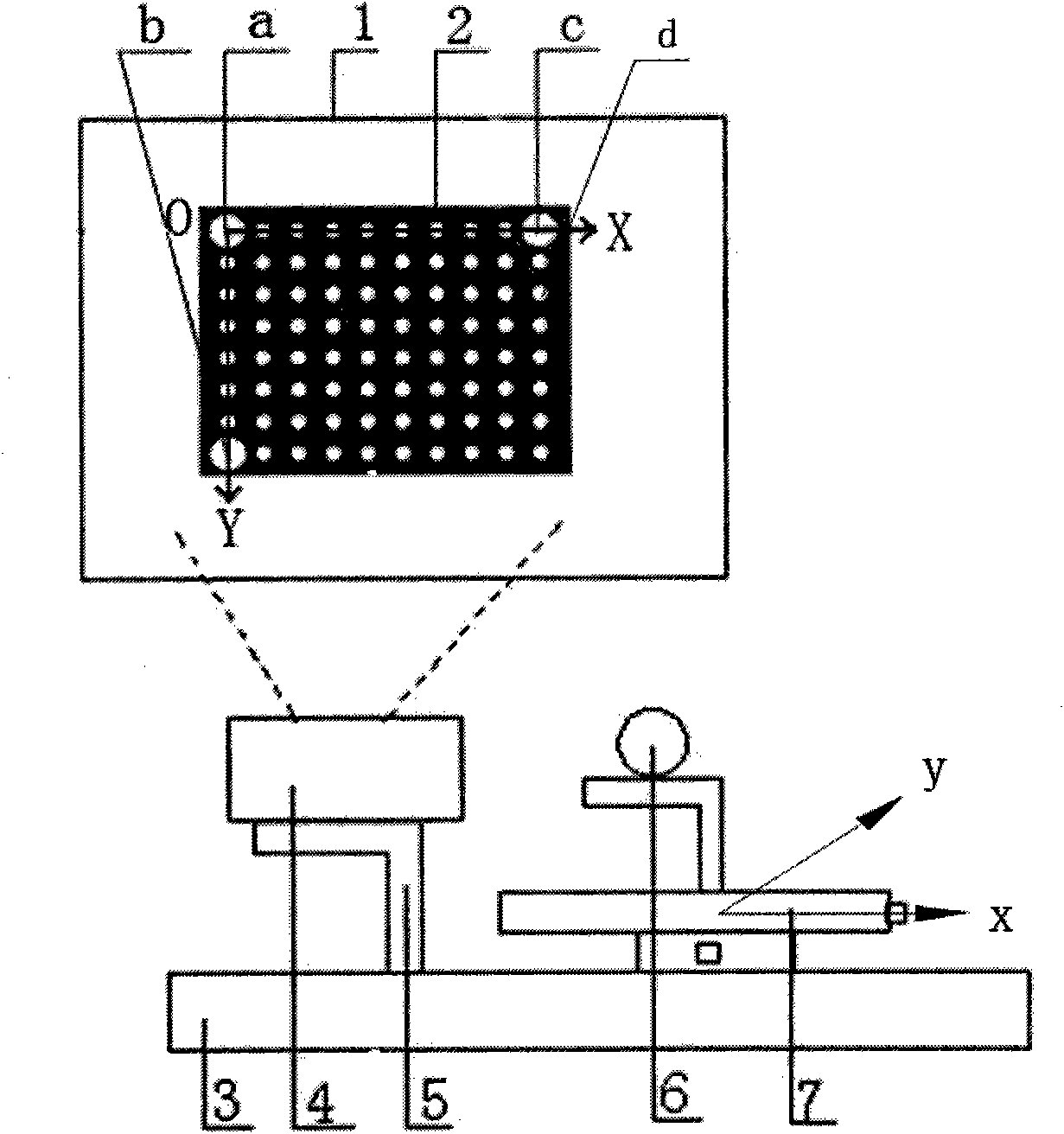
[0030] Step 1: Formulate the calibration target of internal and external parameters of the camera

[0031] First make the calibration target of the internal parameters of the camera, such as figure 2 As shown, there are N rows and M columns of easily identifiable characteristic dots distributed on the target 2 of camera internal parameter calibration, where: the diameters of the first, second, and third positioning circles a, b, and c at the three corners of the array It should be larger than the diameter of other characteristic circles d; establish coordinate system XOY, take O point as the reference, determine the arr...


PUM


Abstract

The invention discloses a camera on-field calibration method in a measuring system, belonging to the field of computer vision detection, in particular to an on-field calibration method for solving inside and outside parameters of cameras in a large forgeable piece size measuring system. Two cameras and one projector are provided in the measuring system. The calibration method comprises the following steps of: manufacturing inside and outside parameter calibration targets of the cameras; projecting inside parameter targets and shooting images; extracting image characteristic points of the images through an image processing algorithm in Matlab; writing out an equation to solve the inside parameters of the cameras; processing the images shot simultaneously by the left camera and the right camera; and measuring the actual distance of the circle center of the target by using a left theodolite and a right theodolite, solving a scale factor and further solving the actual outside parameters. The invention has stronger on-field adaptability, overcomes the influence of impermeable and illegible images caused by the condition that a filter plate filters infrared light in a large forgeable piece binocular vision measuring system by adopting the projector to project the targets, and is suitable for occasions with large scene and complex background.

Description

technical field [0001] The invention relates to the field of computer vision detection. In particular, the invention relates to an on-site calibration method for obtaining internal and external parameters of a camera in a large-scale forging dimension measurement system. Background technique [0002] How to accurately measure large forgings in real time is a difficult point. Measuring large forgings requires large measurement range, high accuracy, on-site measurement, even dynamic measurement and full attitude measurement. The binocular stereo vision measurement and detection method has the characteristics of large range, non-contact, fast measurement speed, good system flexibility and high accuracy, and can well meet the requirements for measuring the geometric parameters of high-temperature and large-size workpieces. [0003] The invention patent of dual camera calibration method in 3D reconstruction system declared by Da Feipeng from Southeast University, the publicatio...

Claims


Application Information

Patent Timeline
Patent Type & Authority Applications(China)
IPC IPC(8): G01B11/00G06T7/00
Inventor 贾振元刘巍杜剑贾兴华刘双军王邦国李朝弟
Owner DALIAN UNIV OF TECH
Why Eureka
Try Eureka