

Device for analyzing analyte in liquid sample
A liquid sample and analyte technology, applied in the field of collecting liquid samples and detecting the analytes in the samples, can solve the problems of operators being polluted by samples, and achieve the effect of improving accuracy and sensitivity and convenient operation.
- Summary
- Abstract
- Description
- Claims
- Application Information
AI Technical Summary
Problems solved by technology
Method used
Image

Examples
Embodiment 1
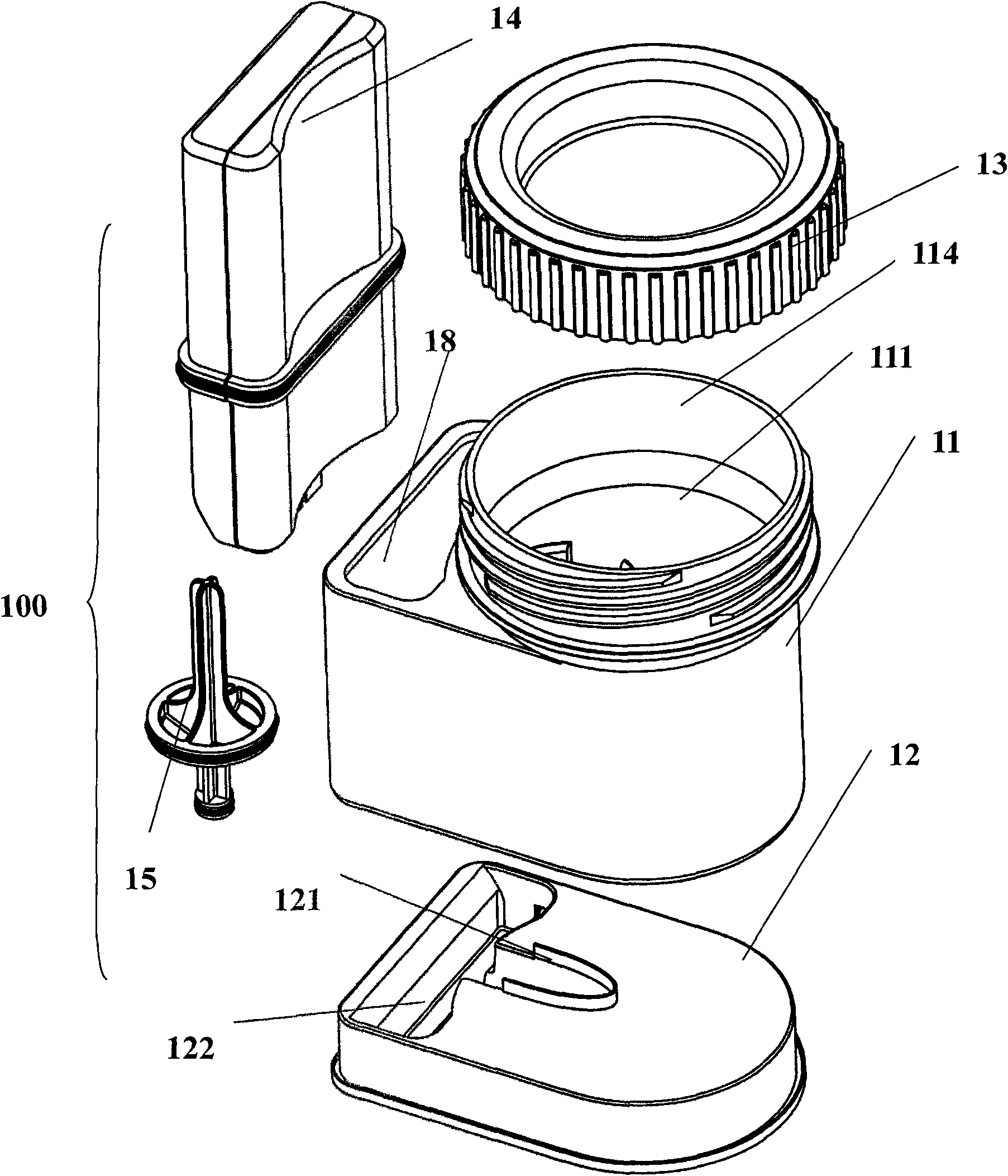
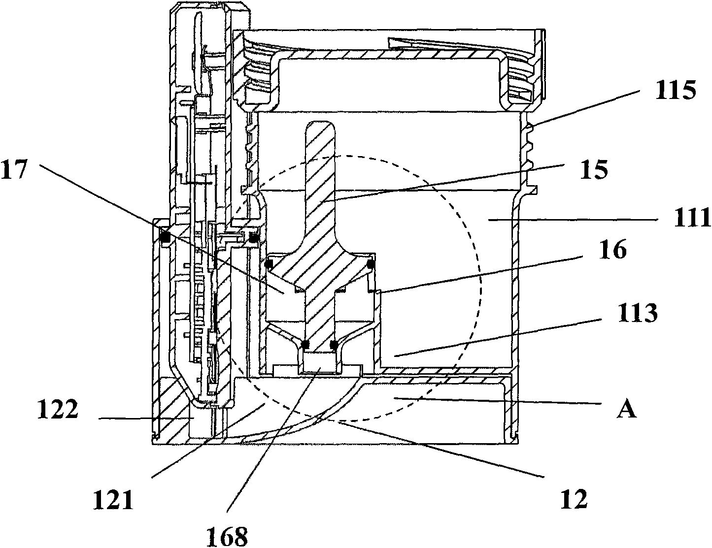
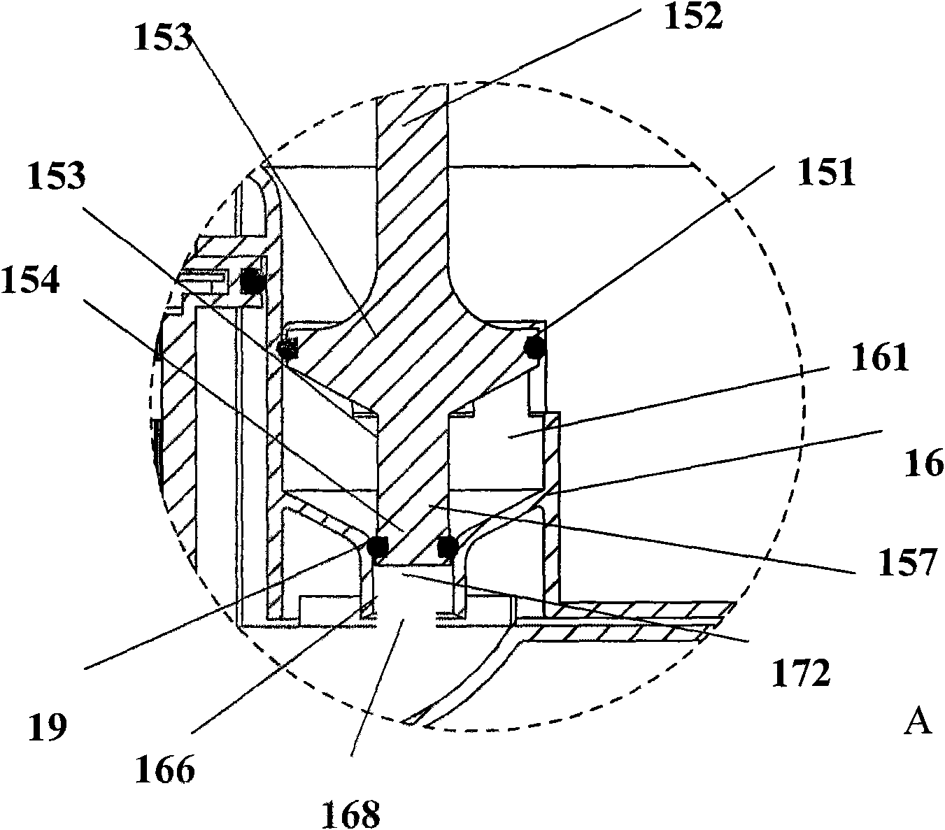
[0051] Such as Figure 1-5 Example 1 is shown. The detection device 100 includes a cup body 11 and a cup cover 13 , the cup body 11 includes a liquid sample collection cavity 111 , a piston cavity 16 and a piston 15 . There are threads on the cover body 13, and threads matched therewith on the cup body 11, and the cover body 13 and the cup body 11 can cooperate and seal each other. A detection cavity 18 for accommodating the detection element 14 is provided on the side wall 115 of the cup body 11 . Two sealing rings 19 are included between the piston 15 and the piston chamber 16, the longitudinal section of the piston chamber 16 and the piston 15 is funnel-shaped, and the transfer is limited between the inner walls 164, 165, 166 of the piston chamber and the outer walls 155, 156, 157 of the piston. Cavity 17. Openings 163 and 168 at both ends of the piston chamber 16 form two openings 171 and 172 of the transfer chamber 17 . One end of the piston 15 has a large diameter an...
Embodiment 2
[0053]The difference from Embodiment 1 is that a push rod 252 is connected to the cover body 23 , and the other end of the push rod 252 is connected to the piston 25 . The piston 25 of the device 200 and the piston cavity 26 corresponding to the piston are cylinders with approximately equal diameters. An opening 251 is included on the piston 25. The diameter at the opening 251 is smaller than the inner diameter of the piston cavity 26. The opening 251 and The inner wall 264 of the piston chamber 26 defines a transfer chamber 27 for transferring the liquid sample from the collection chamber 211 to the detection chamber 28 . Two openings 263 and 268 of the piston 25 form two openings 271 and 272 of the transfer chamber 27 . The piston 25 also includes a protrusion 256 and a bayonet 265 cooperating with the protrusion on the piston cavity. The protrusion 256 and the bayonet socket 265 form a blocking element. When the piston 25 moves from the first position to the second positio...
Embodiment 3
[0055] This example Figure 11-15 As described, the detection device 300 includes a cup body 31 and a cover body 33 , and the cup body 31 includes a liquid sample collection cavity 311 , a piston cavity 36 and a piston 35 . The cover body 33 has threads, and the cup body 31 has threads matched therewith. The cover body 33 and the cup body 31 can cooperate and seal each other. A push rod 331 is arranged on the cover body 33 , one end of the push rod 331 is connected to the cover body 33 , and the other end is used to close the opening 371 of the transfer chamber 37 . At the bottom of the collection chamber 311, a piercing element 366 is arranged to pierce the closed end of the transfer chamber. A detection cavity 18 for accommodating the detection element 14 is provided on the side wall 315 of the cup body 11 . In addition, a hole 367 is opened at the bottom of the collection chamber 36 , through which the liquid from the transfer chamber 37 can enter the detection chamber 38...
PUM
 Abstract
Description
Claims
Application Information