
Satellite laser ranging (SLR) super short distance target calibration method

A satellite laser ranging and ultra-short-range technology, which is used in measurement devices, radio wave measurement systems, and electromagnetic wave re-radiation. clear target effect

Inactive Publication Date: 2010-11-03
INST OF EARTHQUAKE CHINA EARTHQUAKE ADMINISTRATION
View PDF0 Cites 7 Cited by
  • Summary
  • Abstract
  • Description
  • Claims
  • Application Information

AI Technical Summary

Problems solved by technology

[0004] The ground target measurement technology is difficult to maintain due to the long distance between the ground target and the aiming during measurement. In order to solve these problems, in recent years, diffuse reflectors have been used to replace corner reflectors, and the distance has also been moved closer to 100 meters to hundreds of meters. meters, but further moving closer to the target is subject to technical restrictions, the main impact of which is the problem of the distance gate

Method used


Image

  • Satellite laser ranging (SLR) super short distance target calibration method
  • Satellite laser ranging (SLR) super short distance target calibration method
  • Satellite laser ranging (SLR) super short distance target calibration method

Examples


Embodiment Construction

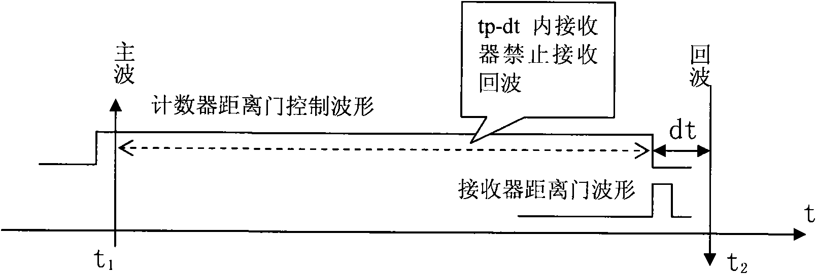
[0013] 1. Range gate generation

[0014] In order to obtain enough time to open the range gate, the present invention uses a signal (leading the main wave) with a causal relationship with the main wave (300-700 ns) in front of the main wave to generate the range gate. The laser involved in the present invention belongs to the Nd:YAG dye passive mode-locking type, and before the laser pulse is generated, a weak laser with a wavelength of 1064nm will be generated near the oscillation level. Usually the main laser pulse is called the main wave, and the laser generated at the oscillation level ahead of the main pulse is called the leading main wave. After testing, there is a strict corresponding relationship between the generation time of the leading main wave, which is used as the trigger signal of the range gate.

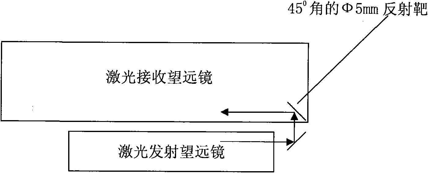
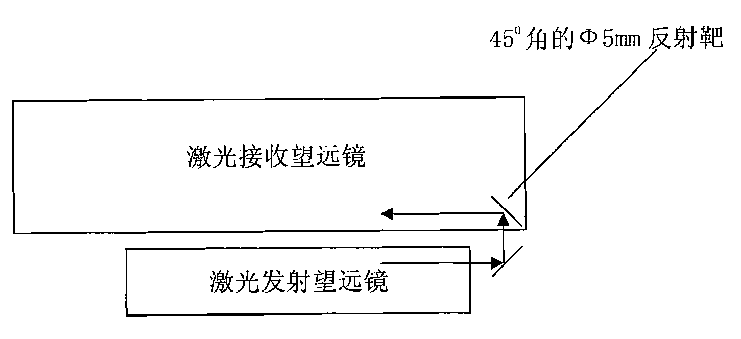
[0015] 2. Close range target design

[0016] In order to reduce the time of target aiming, the target is designed on the receiving lens barrel; at the same time, in...


PUM


Abstract

The invention relates to a super short-distance (less than 1m) target distance measuring technology in satellite laser ranging (SLR), and is composed of a distance gate control mode, and an optical and mechanical structure for calibrating a target. A near-earth target is arranged between a transmitting column and a receiving column of a telescope and can rotate along with the telescope to calibrate time delay of various light paths and circuits in a satellite laser ranging system.

Description

technical field [0001] The invention relates to an ultra-short-range (less than 1m) target distance measuring technology applied in satellite laser ranging (SLR). Background technique [0002] The principle of satellite laser ranging figure 1 shown. at t 1 Aim at the satellite from the ground station at time and fire a laser pulse; at t 2 The laser signal reflected back by the satellite is received at all times, and Δt=(t 1 -t 2 ) / 2 is the time that light takes from the station to the satellite, and the distance from the station to the satellite is d=Δt×C, where C is the speed of light. [0003] The distance value measured in this way includes the transmitting optical path, receiving optical path, and delay on the circuit, and the delay varies with environmental factors such as temperature. In order to deduct it, the usual method is to set a target at a known distance point on the ground, and then measure the target with an instrument to obtain the distance value d 1 ...

Claims


Application Information

Patent Timeline
IPC IPC(8): G01S17/08G01S7/497
Inventor 王培源郭唐永李欣邹彤谭业春李翠霞朱威
Owner INST OF EARTHQUAKE CHINA EARTHQUAKE ADMINISTRATION
Learn More