Capacitive rotation sensor

A rotation sensor, capacitive technology, applied in the direction of conversion sensor output, capacitance measurement, instrument, etc., can solve the problem of rotor disk imbalance or impact, complex structure, lack, etc., to achieve the effect of preventing warping or impact

Inactive Publication Date: 2010-11-03
HENGSTLER GMBH
View PDF8 Cites 4 Cited by
  • Summary
  • Abstract
  • Description
  • Claims
  • Application Information

AI Technical Summary

Problems solved by technology

However, this rotary sensor has its disadvantages: it is rather complex and expensive to produce, since it has to be fulfilled that an outer rotor shaft can only be press-fitted to an inner rotor disk in a press-fit seat. On a vertical flange for mechanical assembly of the rotary sensor
[0003] A disadvantage of the construction described above is that, in the case of a press-fit seat between a vertical flange of the rotor disc and the outer circumference of the rotor shaft, a certain imbalance or shock (wobble error) occurs on the rotor disc , which can only be corrected with difficulty using an analysis processing circuit
[0004] Furthermore, the known arrangement has the disadvantage of lacking a cover that can enclose the entire device, in particular a cover that has a pivot bearing for the rotor shaft in order to be as accurate and aligned as possible. Central and shock-free guidance of the rotor shaft
[0006] Therefore, this system according to the prior art is structurally rather complicated, and the valuation analysis of the angle of rotation is inaccurate

Method used


Image

  • Capacitive rotation sensor
  • Capacitive rotation sensor
  • Capacitive rotation sensor

Examples


Embodiment Construction

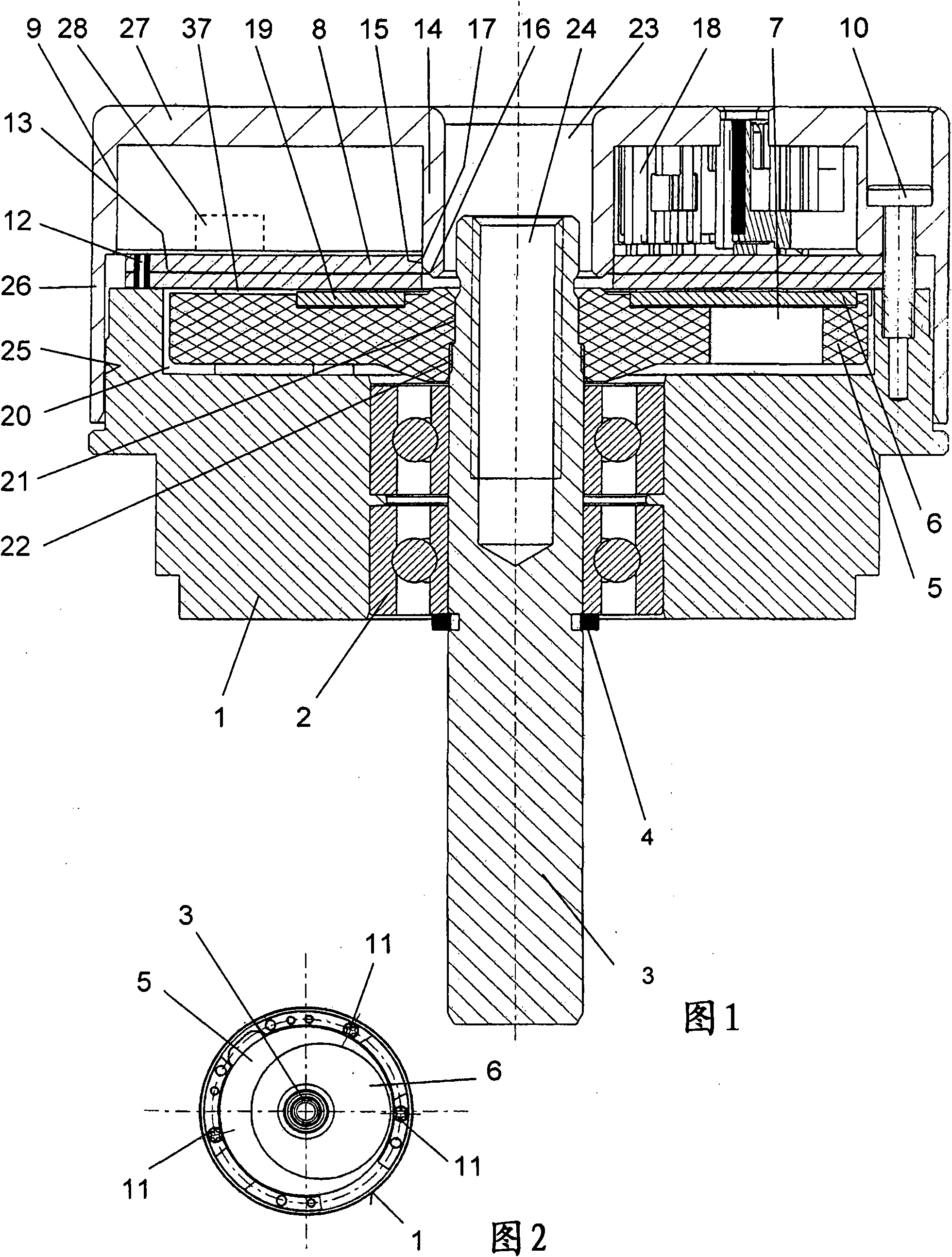
[0057] Such as figure 1 and 2 As shown, the capacitive rotation sensor proposed by the present invention mainly includes a shell flange 1 made of aluminum casting, which is designed to be cylindrical, and a clamping frame is arranged in its inner hole. Tight ball bearings 2 form the device.

[0058] The ball bearing 2 is preferably designed as a deep groove ball bearing. According to another development, it can be provided that the ball bearing is designed as a sliding bearing or generally as a rolling bearing.

[0059] In the interior, a shaft 3 is supported by a ball bearing 2 , which protrudes with a lower extension from the housing of the capacitive rotary sensor and is secured against falling out by means of a locking ring 4 . This locking ring can also be omitted. However, it can be used to additionally absorb the axial forces transmitted by the shaft 3 to the housing flange 1 .

[0060] In a manner that will be described in more detail below, a rotor support 5, pre...


PUM


Abstract

A capacitive rotation sensor for detecting the position of an object moving relative to a stationary object, comprising a shaft rotatably supported in a housing flange, said shaft being connected integral in rotation therewith to a rotor to which, separated by an air gap, a stator situated opposite thereto is assigned, wherein at least the rotor, the stator and an evaluation circuit are enclosed by an electrically conductive cap, wherein a stator surface is arranged on the underside of a circuit board and the stator surface has assigned thereto, situated opposite thereto and separated by the air gap, a non-rotation-symmetrical rotor disc which, in turn, is fixed on a rotor support, said rotor support being fastened highly precisely on the outer periphery of the shaft so as to be integral in rotation therewith.

Description

technical field [0001] The subject of the invention is a capacitive rotation sensor as stated in the preamble of claim 1 . Background technique [0002] Such a capacitive rotation sensor is disclosed, for example, in the context of EP 1173730 B1 (DE 60016395 T2). However, this rotary sensor has its disadvantages: it is rather complex and expensive to produce, since it has to be fulfilled that an outer rotor shaft can only be press-fitted to an inner rotor disk in a press-fit seat. On the vertical flange, in order to realize the mechanical assembly of the rotary sensor. [0003] A disadvantage of the construction described above is that, in the case of a press-fit seat between a vertical flange of the rotor disc and the outer circumference of the rotor shaft, a certain imbalance or shock (wobble error) occurs on the rotor disc , which can only be corrected with difficulty using an analysis circuit. [0004] Furthermore, the known arrangement has the disadvantage of lacking...

Claims


Application Information

Patent Timeline
Patent Type & Authority Applications(China)
IPC IPC(8): H02K11/00
CPCG01R27/2605G01D5/24442G01R27/26G01D5/2415G01D11/245G01R27/02G01D11/30G01D2205/60G01D2205/73
Inventor S·黑尔德J·比歇尔A·韦尔施泰因
Owner HENGSTLER GMBH
Why Eureka
Try Eureka