Structure of stand-riding bicycle

A bicycle and frame technology, applied in the field of bicycle structure, can solve the problems of lowering the standing position, not being able to go up and down, and not being able to make full use of it, so as to reduce the protruding feeling and utilize physical strength.

Inactive Publication Date: 2010-11-10
滨田荣一
View PDF7 Cites 4 Cited by
  • Summary
  • Abstract
  • Description
  • Claims
  • Application Information

AI Technical Summary

Problems solved by technology

In this method, the foot support panel itself, which is slender in the front-rear direction, has the hinge as the center of rotation for reciprocating motion, so it has the advantage of having a clean appearance and lowering the standing position of the occupant. In addition, the driving mechanism is also hidden in the However, there are also problems such as the following: the foot support surface plate must be at the bottom dead center when it is in a roughly horizontal state, so the reciprocating motion only utilizes the roughly upper half of the arc track and cannot fully utilize the upper and lower components. There are many parts, and in order to establish the linkage mechanism of the movement of the left and right footrest surface plates based on the operation of the drive mechanism, the fixed objects protruding upward from the frame on the center line of the vehicle not only affect the clean footrest surface In addition, the occupant is required to pay extra attention to contact when stepping on the pedals. In addition, the miniaturization of the steering shaft when it is folded and stored is restricted.
In addition, the angle of the foot support surface plate is determined geometrically. Therefore, if the size in the front and rear directions is reduced, the up and down stroke cannot be obtained, or the angle of the foot where the occupant tends to exert force cannot be freely obtained.

Method used


Image

  • Structure of stand-riding bicycle
  • Structure of stand-riding bicycle
  • Structure of stand-riding bicycle

Examples


Embodiment

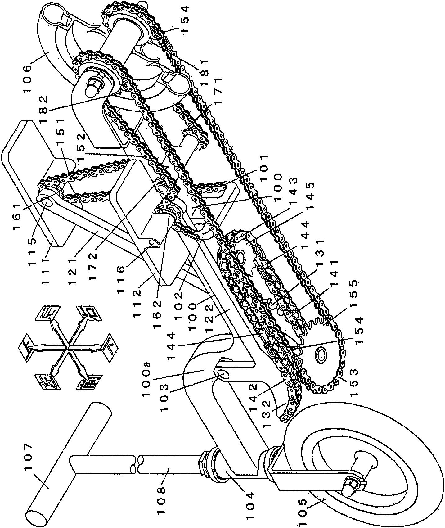
[0076] figure 1 It is an isometric projection drawing which shows one Embodiment of 1st invention. The occupant holds the handle 107 and rides the vehicle in a posture of standing on the pedals 111 / 112. First, the interlocking mechanism of the up-and-down reciprocating motion of the left and right pedals will be described. When the pedal (right) 111 is depressed, the pedal arm (right) 121 rotates around the pedal arm rotating shaft 103 disposed on the frame upright portion 100a, and the sprocket function portion (right) 131 integrated therewith rotates to rotate. The arm chain (right) 141 is stretched forward, and the U-shaped rotary chain 143 connected to it through the orthogonal joint 144 is rotated in a U-shape on the epicyclic sprocket 145, and the opposite side is connected through the orthogonal joint 144. The arm chain (left) 142 is pulled rearward to drive the sprocket function part (left) 132, the pedal arm (left) 122 is rotated, and the pedal (left) 112 and the sw...


PUM


Abstract

The present invention provides a technique for implementing a stand-riding bicycle by using a miniaturization and beautiful configuration. The bicycle is advanced through pedal reciprocation caused by a pedal angle and a pedal track which facilitate the force application of a rider. A rotating shaft is arranged on front of and above a pedal foot face on the lower dead point. Pedals and swinging chain wheels (161 / 2) are arranged on the top and bottom of the rear part of left and right pedal arms which are mechanically linked in a mode that the swinging movement is of a direction opposite to the advance direction. Chain anchoring devices (101 / 2) and Idler chain wheels (171 / 2) are arranged on a bicycle frame on front and back ends of the swinging chain wheels and below the pedal on the lower dead point. One ends of left and right driving chains are fixed by the chain anchoring devices, the left and right driving chains are coiled on the swinging chain wheels, the Idler chain wheels and the one-way clutch chain wheels (181 / 2) in sequence, so as to form the other end facing forwards, the other end is respectively connected with two ends of a U-shaped return chain which returns in an U shape on the front, such that the left and right parts are connected.

Description

technical field [0001] The present invention relates to a bicycle structure in which left and right pedals on which a occupant is standing are propelled by reciprocating up and down. Background technique [0002] Conventional bicycles generally have a mechanism in which a rider sits on a seat, rotates a crank arm with his feet, and transmits the rotation to a rear wheel through a chain or the like to propel it. The seated riding posture can reduce the physical burden of maintaining the posture, but it is difficult to use the body weight for the rotation of the crank arm. Therefore, when a large propulsion force is required, although the method of shifting gear or standing pedal can be used, but, The reduction of the propulsion force near the upper and lower dead centers of the crank arm rotation is inevitable. In addition, since the saddle is provided on the frame, the miniaturization of the bicycle is restricted. [0003] In order to make up for the above-mentioned shortc...

Claims


Application Information

Patent Timeline
Patent Type & Authority Applications(China)
IPC IPC(8): B62M1/04B62M1/24
CPCB62K3/002B62K17/00B62M1/28
Inventor 滨田荣一
Owner 滨田荣一
Why Eureka
Try Eureka