
Roll-on device and method for large fixed type rotary crane

A crane and fixed technology, applied in the direction of cranes, hoisting devices, hoisting equipment braking devices, etc., can solve the problems of difficulty in ensuring the accuracy of floating crane operations, increasing the manufacturing cost of the whole machine, and prolonging the on-site operation time. Achieve the effect of saving user docks, low transportation and installation costs, and short installation period

Active Publication Date: 2010-11-10
DALIAN HUARUI HEAVY IND GRP CO LTD
View PDF5 Cites 16 Cited by
  • Summary
  • Abstract
  • Description
  • Claims
  • Application Information

AI Technical Summary

Problems solved by technology

On-site installation needs to use a large floating crane for installation and alignment, and the installation cost is particularly high. In addition, the floating crane operation is seriously affected by the weather, and it is difficult to ensure the accuracy of the floating crane operation
At the same time, it also leads to longer on-site operation time, prolongs the delivery time of the equipment, and increases the cost of the whole machine manufacturing

Method used


Image

  • Roll-on device and method for large fixed type rotary crane
  • Roll-on device and method for large fixed type rotary crane
  • Roll-on device and method for large fixed type rotary crane

Examples


Embodiment Construction

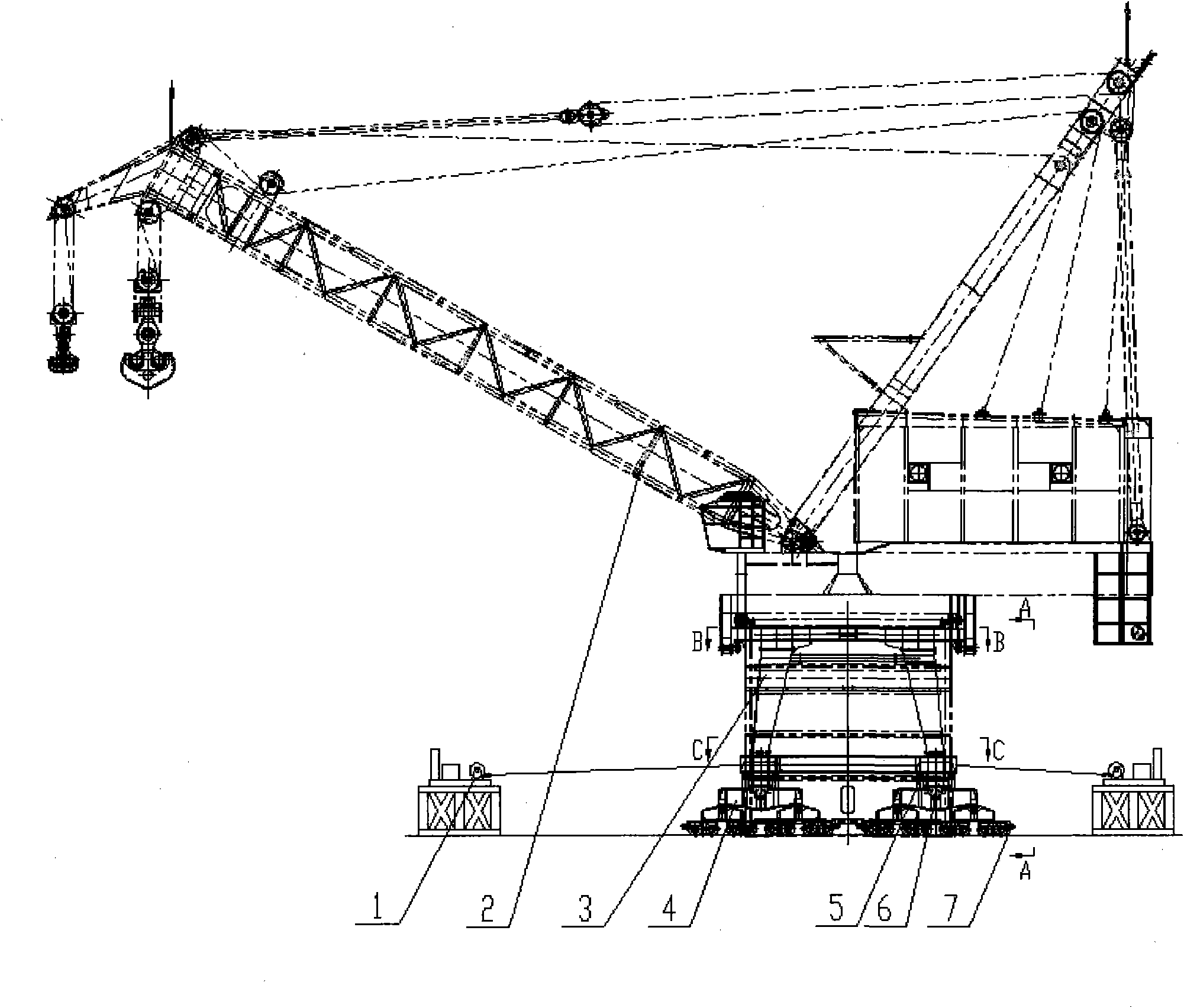
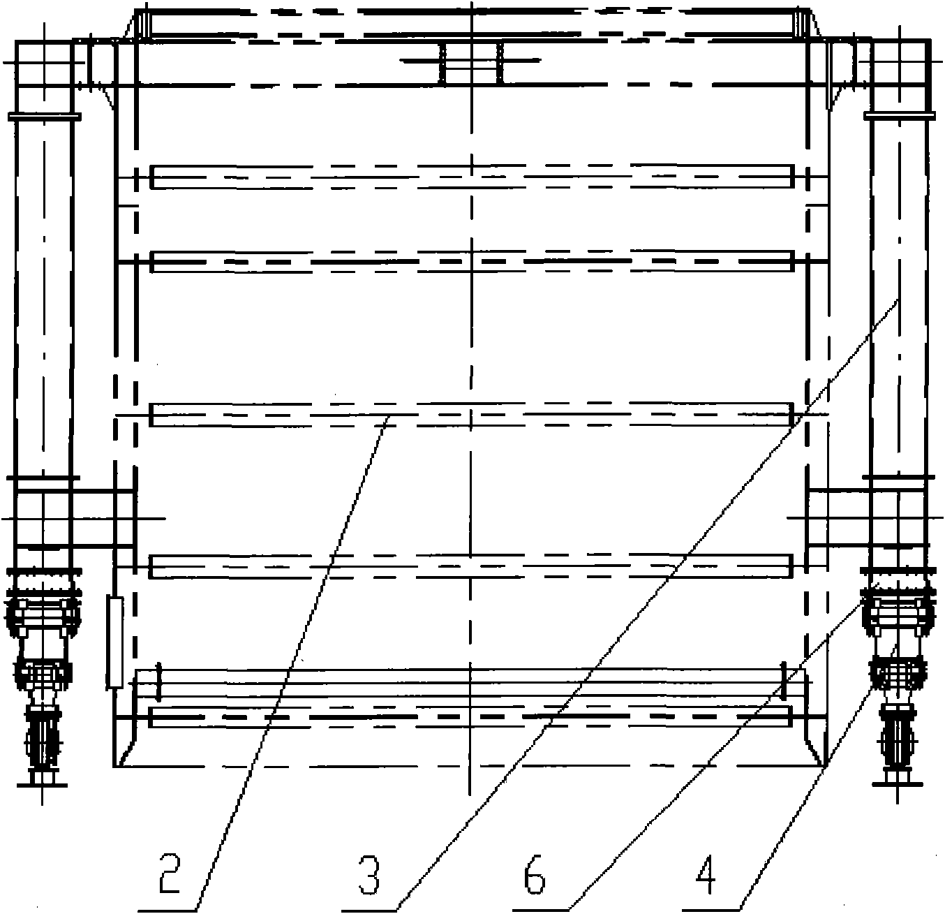
[0031] Such as Figure 1 to Figure 8 The shown roll-on-roll-off device for a large fixed slewing crane is mainly composed of a hoist 1 , a crane body 2 , a rigid mast 3 , a running trolley group 4 , a jack 5 , an adjustment pad 6 , and a wheel brake 7 .

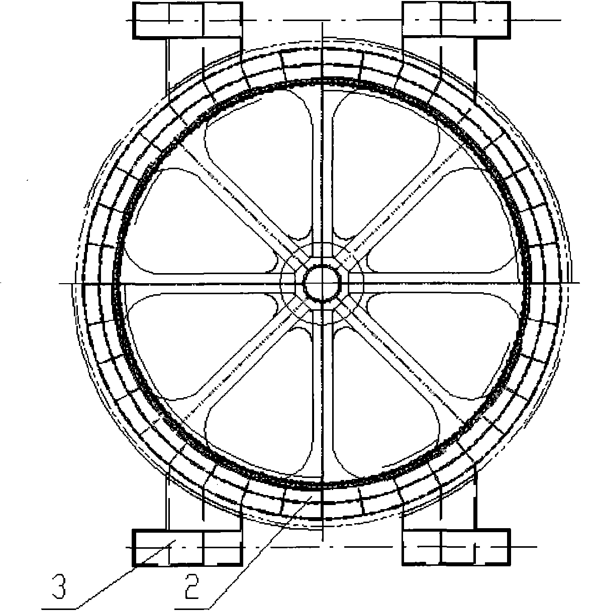
[0032] The crane main body 2 includes cylindrical steel structure 2.1, slewing support device 2.2, slewing turntable 2.3, jib frame 2.4, herringbone frame 2.5, machine room 2.6 and other components, see Image 6 Among them, the cylindrical steel structure 2.1 will be fixed to the user's dock, and the slewing support device 2.2 is used to connect the rotary turntable 2.3 and the cylindrical steel structure 2.1, the rotary turntable 2.3, the arm frame 2.4, the herringbone frame 2.5, and the machine room 2.6 The superstructure of equal composition can be 360 ​​° of revolutions around the center of revolution under the bearing of slewing support device 2.2. Boom 2.4 and herringbone frame 2.5 are respectively connected with slewi...


PUM


Abstract

The invention discloses roll-on device and method for a large fixed type rotary crane, which is characterized in that the roll-on device mainly comprises two groups of hoists, two groups of rigid gantries, four running trolley groups, eight jacks, a regulation poppet and a wheel-sided brake, wherein each rigid gantry consists of a shoulder bracket welded on the main body of a crane, support columns connected with the shoulder bracket and a sill beam arranged below the gantry legs, and the sill beam is connected with a support bracket welded on the main body of the crane through bolts; and each running trolley group comprises an upper equalizer, an intermediate equalizer, a trolley and hinged shafts of various grades. The two groups of the rigid gantries are symmetrically installed on two sides of the main body of the crane, the four running trolley groups are connected with the regulation poppet through bolts and bolted below the rigid gantries, the eight jacks are symmetrically installed between the gantries and the trolley groups, the two groups of winches are respectively arranged on the front and the back of the main body of the crane, and during rolling on, the winch at one side draws to move the main body of the crane, and the winch at the other side plays the role of braking. Through regulating the jacks, the regulation poppet is withdrawn so as to ensure that the main body of the crane is in position for installation.

Description

technical field [0001] The invention relates to lifting and transporting machinery, in particular to the transport and installation of a large fixed slewing crane used for loading and unloading heavy parts in ports and docks. Background technique [0002] Large fixed slewing cranes are ship unloading equipment widely used in heavy cargo wharfs, especially with the development of nuclear power projects in China and the start of large steel plant projects, some heavy key nuclear facilities and key equipment of large steel plants are of great importance to this type of crane Demand, and used as a heavy lifting equipment fixed on the wharf. This kind of crane has a large lifting capacity, and because of its special nature of work, there is no special operating mechanism for the whole machine. For the transportation of this kind of products, the transportation scheme currently adopted is bulk transportation or large-scale transportation, and its transportation cost and on-site i...

Claims


Application Information

Patent Timeline
Patent Type & Authority Applications(China)
IPC IPC(8): B66C5/02B66D1/60B66C23/16
Inventor 申小强胡光宏边桂显
Owner DALIAN HUARUI HEAVY IND GRP CO LTD
Learn More