Electric system modeling method and system

A power system and modeling method technology, applied in information technology support systems, electrical digital data processing, special data processing applications, etc., can solve problems such as low efficiency, tedious and complex processes, and workload, and reduce workload. , Improve efficiency, convenient and quick workload effect

Active Publication Date: 2010-11-10
ZHONGSHAN POWER SUPPLY BUREAU OF GUANGDONG POWER GRID
View PDF5 Cites 16 Cited by
  • Summary
  • Abstract
  • Description
  • Claims
  • Application Information

AI Technical Summary

Problems solved by technology

In the existing field of power system modeling, automation personnel start modeling the power system locally, first modeling the electrical components in the substation, and then combining multiple electrical components into an interval model, and then Multiple bays are connected through busbars and transformers to form a substation model, that is, after storing the information of each electrical component in the database, a bay model is built for each electrical component in the database, and then a substation model is generated. The modeling method needs to perform many repeated modeling operations on electrical components, and then build intervals for each electrical component. The process is cumbersome and complicated, which consumes a lot of work and is inefficient.
In fact, by comparing and analyzing the various models of the substation, it will be found that in the same substation, the same voltage level, the same type (with the same topology) of the interval, many of their parameters are the same, for example, which Devices need to collect telemetry, which devices need to collect telesignals, which protection signals are in this interval, etc. These parameters are basically the same, that is to say, this modeling method in the existing technology is actually repeated a lot If the substation can be modeled with intervals instead of electrical components as the basic unit, the efficiency of power modeling will be greatly improved. At present, there is no effective power system construction with intervals as the basic unit. Modular schemes emerge

Method used


Image

  • Electric system modeling method and system
  • Electric system modeling method and system
  • Electric system modeling method and system

Examples


Embodiment 1

[0042] Such as figure 2 As shown, it is a schematic flowchart of Embodiment 1 of the power system modeling method of the present invention. In this embodiment, a new interval is generated by searching a database.

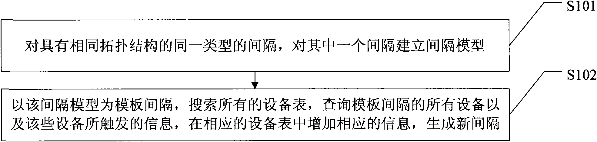
[0043] Such as figure 2 As shown, the power system modeling method in this embodiment includes steps:

[0044]Step S101: For the same type of compartments with the same topology, build a compartment model for one of the compartments, and proceed to step S102;

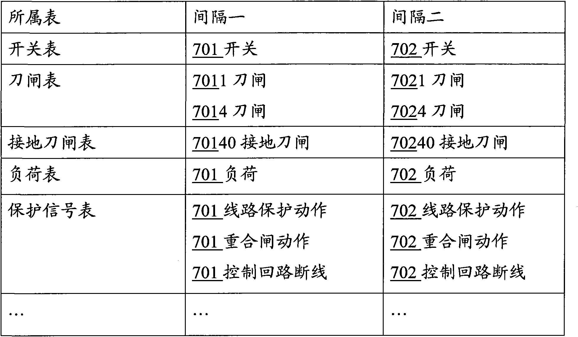
[0045] Step S102: Using the interval model as a template interval, search all equipment tables in the database, query all equipment in the template interval and the information triggered by these equipment, and add the corresponding information of the new interval in the corresponding equipment table to generate new interval.

[0046] In the solution of this embodiment, when an interval model is selected as the template interval, all equipment tables are first searched to find all the equipment in this t...

Embodiment 2

[0050] Such as image 3 Shown is a schematic flow chart of Embodiment 2 of the power system modeling method of the present invention. In this embodiment, a new interval is generated by using the operations performed on the database when establishing the interval as template parameters.

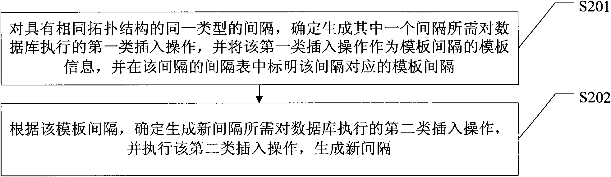
[0051] Such as image 3 As shown, the power system modeling method in this embodiment includes steps:

[0052] Step S201: For intervals of the same type with the same topology, determine the first type of insert operation that needs to be performed on the database to generate one of the intervals, and use the first type of insert operation as a template parameter of the template interval, and in the interval Indicate the template interval corresponding to the interval in the interval table of the interval table, enter step S202;

[0053] Step S202: According to the template interval, determine the second type of insertion operations required to generate a new interval, and execute the second...

Embodiment 3

[0058] Such as Figure 4 As shown, it is a schematic flow chart of the third embodiment of the power system modeling method of the present invention. In this embodiment, when establishing intervals, the operations performed by the database are used as template parameters and the search operation for the database is effectively combined. two ways.

[0059] Such as Figure 4 As shown, the power system modeling method in this embodiment includes steps:

[0060] Step S301: For intervals of the same type with the same topology, determine the third type of insert operations to be performed on the database to generate a fixed amount in one of the intervals, and the first type of insert operations required to generate a variable amount in this interval Search operation, and use the third type of insert operation and the first type of search operation as the template information of the template interval, and indicate the template interval corresponding to the interval in the interval...


PUM


Abstract

The invention provides electric system modeling method and system. The electric power modeling system is modeled by using an interval as a basic unit. Aiming at the intervals of same type with same topological structure, an interval model is established for one of the intervals of the type, then other intervals are generated by using the interval model, and a substation model is formed by connection of buses, transformers and the like by using the intervals after the intervals are generated. For the intervals of the same type, the topological structures and many parameters are same, other intervals are generated by using one interval model as a template interval, therefore, the invention has convenient and quick operation and less workload; and compared with the traditional modeling mode using an electric element as a basic unit, the invention greatly reduces the workload and improves the efficiency of the electric power modeling.

Description

technical field [0001] The invention relates to the field of electric power automation, in particular to a power system modeling method and a power system modeling system. Background technique [0002] Power system modeling is the basis of power system calculation, analysis and control. How to effectively model is an important content that must be considered in power system automation. In the existing field of power system modeling, automation personnel start modeling the power system locally, first modeling the electrical components in the substation, and then combining multiple electrical components into an interval model, and then Multiple bays are connected through busbars and transformers to form a substation model, that is, after storing the information of each electrical component in the database, a bay model is built for each electrical component in the database, and then a substation model is generated. In the modeling method, it is necessary to perform many repeat...

Claims


Application Information

Patent Timeline
Patent Type & Authority Applications(China)
IPC IPC(8): G06F17/50
CPCY02E60/76Y04S40/22Y02E60/00
Inventor 邱军旗
Owner ZHONGSHAN POWER SUPPLY BUREAU OF GUANGDONG POWER GRID
Why Eureka
Try Eureka