Nonvolatile semiconductor photorefractive memory structure
A non-volatile, semiconductor technology, applied in the field of medium refractive index, can solve the problems of low efficiency, weak refractive index of optical waveguide, small coupling part, etc., and achieve the effect of high efficiency, energy saving and broad application prospects.
- Summary
- Abstract
- Description
- Claims
- Application Information
AI Technical Summary
Problems solved by technology
Method used
Image
Examples
Embodiment 1
[0028] Embodiment 1 General structure of the present invention
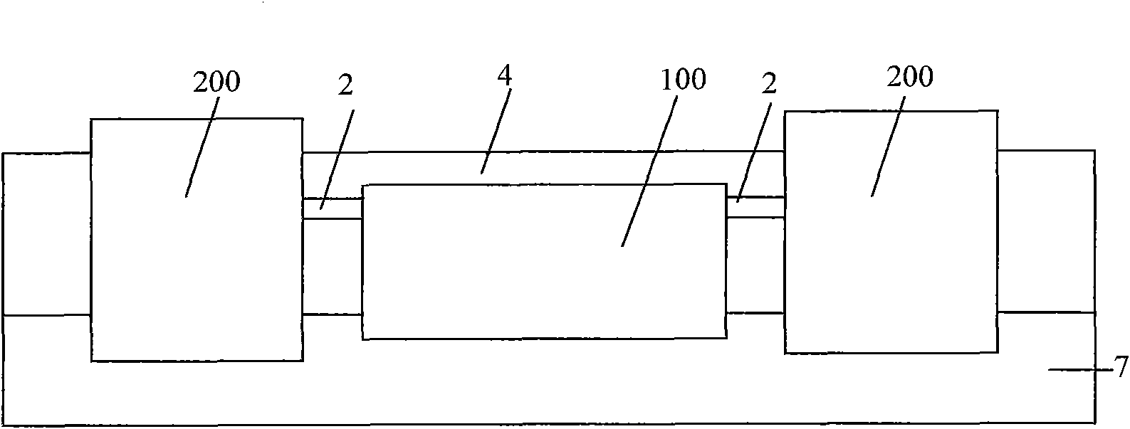
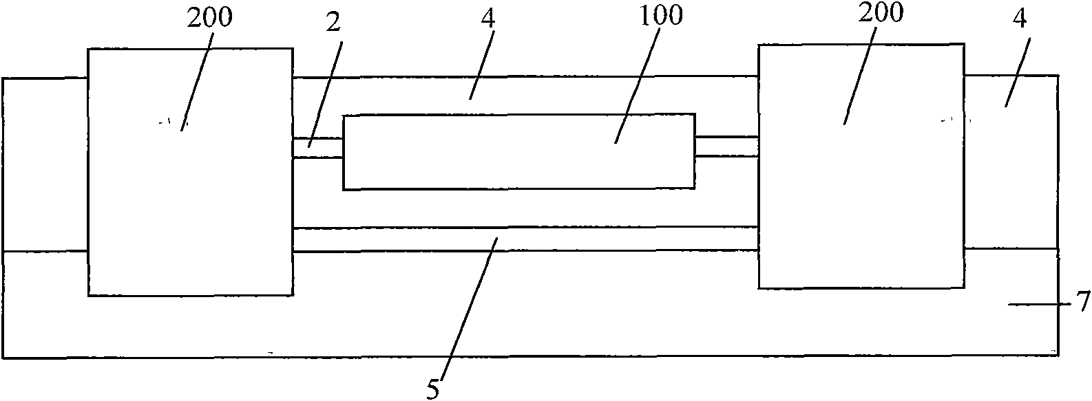
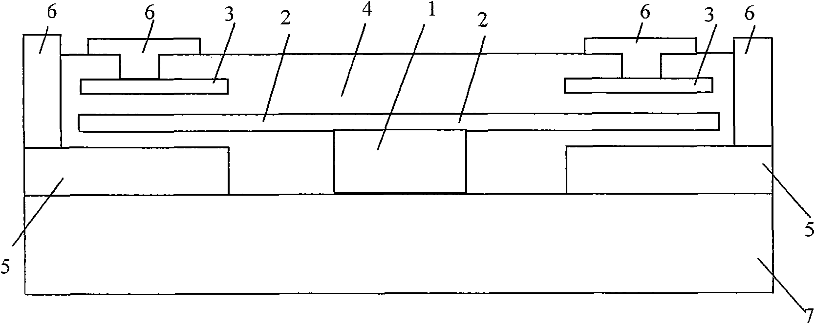
[0029] figure 1 , 2, 3 respectively give the overall structure of the present invention from different angles. In the figure, 100 is an optical waveguide part, 200 is a floating gate part, 1 is a semiconductor optical waveguide, 2 is a floating gate, 3 is a control gate, 4 is an upper insulator medium, 5 is a conductive medium, 6 is an electrode, and 7 is a lower insulator medium.
[0030] The nonvolatile semiconductor photorefractive memory structure of the present invention is composed of an optical waveguide part 100 and a floating gate part 200 . exist figure 1 , 2 In the structure shown in , 3, there are two floating gate parts 200 . Wherein, the optical waveguide part 100 is made up of the semiconductor optical waveguide 1, the upper insulator medium 4 above the semiconductor optical waveguide 1 and the lower insulator medium 7 below the semiconductor optical waveguide 1; the floating gate part 200 is...
Embodiment 2
[0033] Embodiment 2 Different structures of the optical waveguide part 100
[0034] Figure 4 , 5 , 6, and 7 respectively show the optical waveguide part 100 with different structures.
[0035] Figure 4 As shown, the semiconductor optical waveguide 1 is a strip waveguide, the floating gate 2 is in direct contact with the semiconductor optical waveguide 1, and the floating gates 2 in the two floating gate parts are connected together. The upper insulator dielectric 4 and the lower insulator dielectric 7 electrically isolate the semiconductor optical waveguide 1 and the floating gate 2 from other components.
[0036] Figure 5 As shown, the semiconductor optical waveguide 1 is a ridge waveguide, the floating gate 2 is in direct contact with the semiconductor optical waveguide 1 on the ridge of the semiconductor optical waveguide 1, and the rest are the same Figure 4 .
[0037] Figure 6 As shown, the semiconductor optical waveguide 1 is an inverted ridge waveguide, the ...
Embodiment 3
[0040] Embodiment 3 Different structures of the floating gate part 200
[0041] Figure 8 with Figure 9 The structure of each floating gate portion 200 is drawn. The position of each component is that an electrode 6 contacts the control grid 3, the floating grid 2 is below it, and the conductive medium 5 is below it, and the conductive medium 5 is in contact with another electrode 6; the floating grid 2, the control grid 3 and the conductive medium 5 The insulator medium 4 is electrically isolated.
[0042] Figure 8 and Figure 9 The only difference is that the conductive medium 5 is only in its own floating gate part 200 (such as Figure 8 shown) and the conductive medium 5 is extended to the outside of the floating gate part 200 of itself (as Figure 9 (shown at the left end of the middle conductive medium 5 ), can be integrated with another conductive medium 5 and electrically isolated from the semiconductor optical waveguide 1 .
PUM
 Abstract
Description
Claims
Application Information
 - R&D
- Intellectual Property
- Life Sciences
- Materials
- Tech Scout
- Unparalleled Data Quality
- Higher Quality Content
- 60% Fewer Hallucinations
Browse by: Latest US Patents, China's latest patents, Technical Efficacy Thesaurus, Application Domain, Technology Topic, Popular Technical Reports.
© 2025 PatSnap. All rights reserved.Legal|Privacy policy|Modern Slavery Act Transparency Statement|Sitemap|About US| Contact US: help@patsnap.com


