Automatic circular seam welding pipe tongs

A technology of automatic welding and pipe tongs, applied in welding equipment, auxiliary welding equipment, welding/cutting auxiliary equipment, etc., can solve problems such as low welding efficiency, difficult welding process, and difficult quality assurance, so as to improve work efficiency and shorten installation time. The effect of clamping time and high processing accuracy

Active Publication Date: 2010-11-17
KUSN HUAHENG ENG TECH CENT
View PDF6 Cites 27 Cited by
  • Summary
  • Abstract
  • Description
  • Claims
  • Application Information

AI Technical Summary

Problems solved by technology

Due to the large number and size of elbows and/or flanges, it brings great difficulties to the welding process
The traditional welding method has been carried out by manually rotating the workpiece and manual welding, which not only increases the labor intensity, but also makes the operation inconvenient, and the welding efficiency is low, the level of manual welding is different, and the quality is difficult to guarantee
Even if the commonly used positioner, roller f

Method used


Image

  • Automatic circular seam welding pipe tongs
  • Automatic circular seam welding pipe tongs
  • Automatic circular seam welding pipe tongs

Examples


Embodiment 1

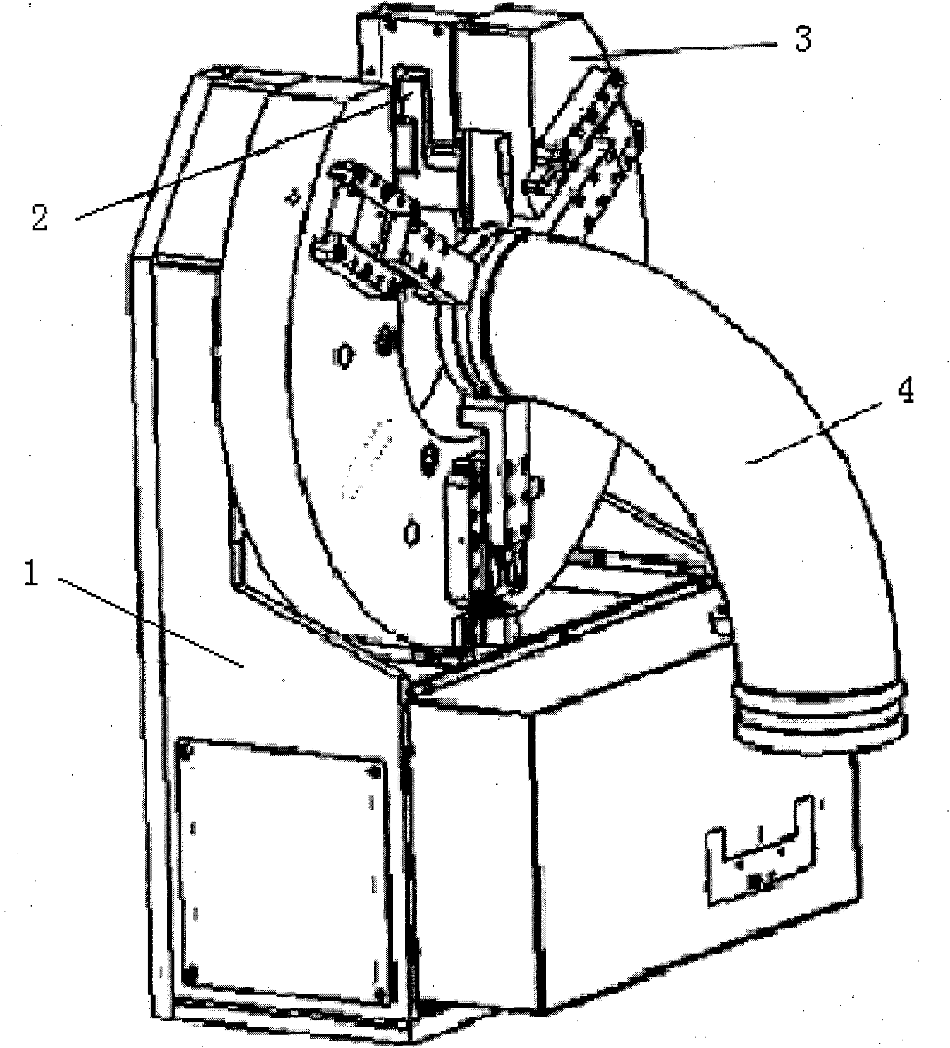
[0025] Such as figure 1 As shown, the circular seam automatic welding pipe tongs of the present invention is a welding tool used for automatic welding of the internal and external angle circular seams of pipe fittings or flanges. One side of the driving and rotating mechanism 2 is connected and fixed with the U-shaped base box 1. The other end of the driving and rotating mechanism 2 is connected to a self-centering positioning and clamping mechanism 3 , and the workpiece 4 is clamped in the self-centering positioning and clamping mechanism 3 .

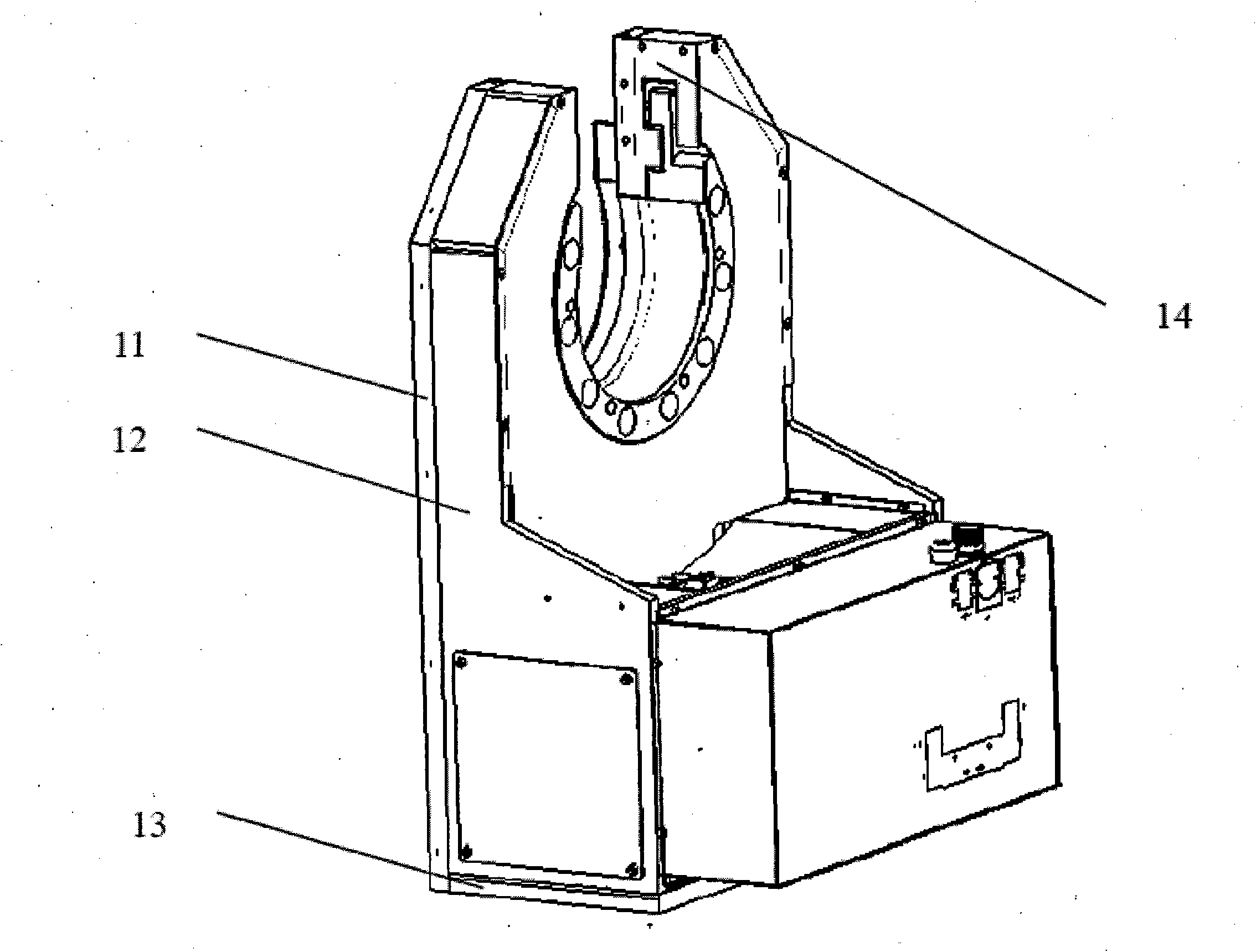
[0026] Such as figure 2 As shown, the U-shaped base box 1 is welded by a main board 11 , a side board 12 , a bottom board 13 and a sealing board 14 , and a U-shaped groove is opened at one end of the main board. In order to enhance the structural strength of the box, stiffener plates can also be welded at appropriate positions.

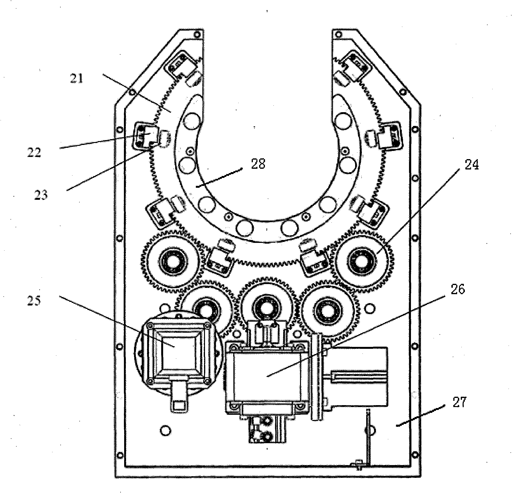
[0027] Such as image 3 , Figure 4 As shown, the drive and rotation mechanism 2 includes a rotary rin...

Embodiment 2

[0032] On the basis of Example 1, the preferred embodiment of the present invention is, as Figure 3-Figure 5 As shown, there are five transition gears 23, which are in external mesh with each other in turn, and the two transition gears 23 at both ends are in external mesh with the rotating ring gear 21.

[0033] The three-jaw guide mechanism 32 comprises four guide plates 35 and five guide blocks 36, and the chute 37 corresponding to the guide blocks 36 is also five, and the two ends of the guide plates are all provided with U-shaped grooves, which are connected with the guide blocks 36 at intervals. Top board 31 is three pieces.

[0034] After the jacking drive 26 is started, it moves upwards to contact the adjustment locking screw 34, and pushes the adjustment locking screw 34 to contact the guide block in the middle of the five guide blocks 36 in the three-claw guide mechanism 32. The middle guide block 36 moves along the chute 37. Moving up (that is, moving toward the ce...


PUM


Abstract

The invention discloses automatic circular seam welding pipe tongs and relates to processing equipment for automatically welding circular seams of elbows/flanges, belonging to the technical field of welding processing equipment. The welding pipe tongs are characterized in that the main body of a driving and rotating mechanism is a bracket with a U-shaped groove, and one side of the bracket is connected and fixed with a U-shaped base box body, while the other side is provided with a rotary gear ring, a supporting seat, a roller bearing, a transition gear, a drive device and a jacking drive, wherein a driving shaft of the drive device is connected with the transition gear, the transition gear is externally engaged with the rotary gear ring, and the rotary gear ring is supported by the supporting seat and the roller bearing which are distributed along the circumference of the rotary gear ring; and a self-centered positioning and clamping mechanism is arranged in the rotary gear ring. Thewelding tool can clamp and rotate an elbow/flange to be welded and realize manual welding and ensures that circular welding seams of elbows/flange inner corners/outer corners can be automatically welded, thereby the labor intensity of workers is reduced, the clamping number of times is reduced, and the welding quality and efficiency are improved.

Description

technical field [0001] The invention relates to a process equipment for automatic welding of elbow / flange ring seams, and belongs to the technical field of welding process equipment. Background technique [0002] In the mechanical equipment used in shipyards, petroleum, petrochemical, chemical, power plants and other industries, there are often a large number of circular components such as elbows and / or flanges. In the process of processing, manufacturing and assembling these equipment, these elbows need to be and / or two girth welds at the inner and outer corners of the flange. Due to the many specifications and different sizes of elbows and / or flanges, it brings great difficulties to the welding process. The traditional welding method has always been carried out by manually rotating the workpiece and manual welding, which not only increases the labor intensity, but also is inconvenient to operate, and the welding efficiency is low, the level of manual welding is different,...

Claims


Application Information

Patent Timeline
IPC IPC(8): B23K37/053
Inventor 汪忠廖剑雄汪魁
Owner KUSN HUAHENG ENG TECH CENT
Why Eureka
Try Eureka