Antigravity dilute-phase pneumatic conveying device for fluid

A pneumatic conveying and anti-gravity technology, which is applied in the direction of conveying bulk materials, conveyors, transportation and packaging, etc., can solve the problems of cultivated land occupation, low yield, drop in the bucket, etc., and achieve the effect of cost saving, simple structure and powerful function

Inactive Publication Date: 2010-11-17
SHANGHAI UNIV
View PDF0 Cites 1 Cited by
  • Summary
  • Abstract
  • Description
  • Claims
  • Application Information

AI Technical Summary

Problems solved by technology

[0005] Humans use pipelines and ditches to transport and utilize water, so a lot of cultivated land is occupied, and because of the complex topography and features of the ground, the construction of water conservancy projects not only requires a lot of investment, but also has little effect
[0006] Especially for some meteorological disasters, such as drought, once it breaks out, it is difficult to alleviate the disaster through water conservancy projects in a short period of time, and the method of motorized transportation is obviously useless and useless. , a large number of real-time transfer of water has become an urgent problem to be solved

Method used


Image

  • Antigravity dilute-phase pneumatic conveying device for fluid
  • Antigravity dilute-phase pneumatic conveying device for fluid
  • Antigravity dilute-phase pneumatic conveying device for fluid

Examples


Embodiment 1

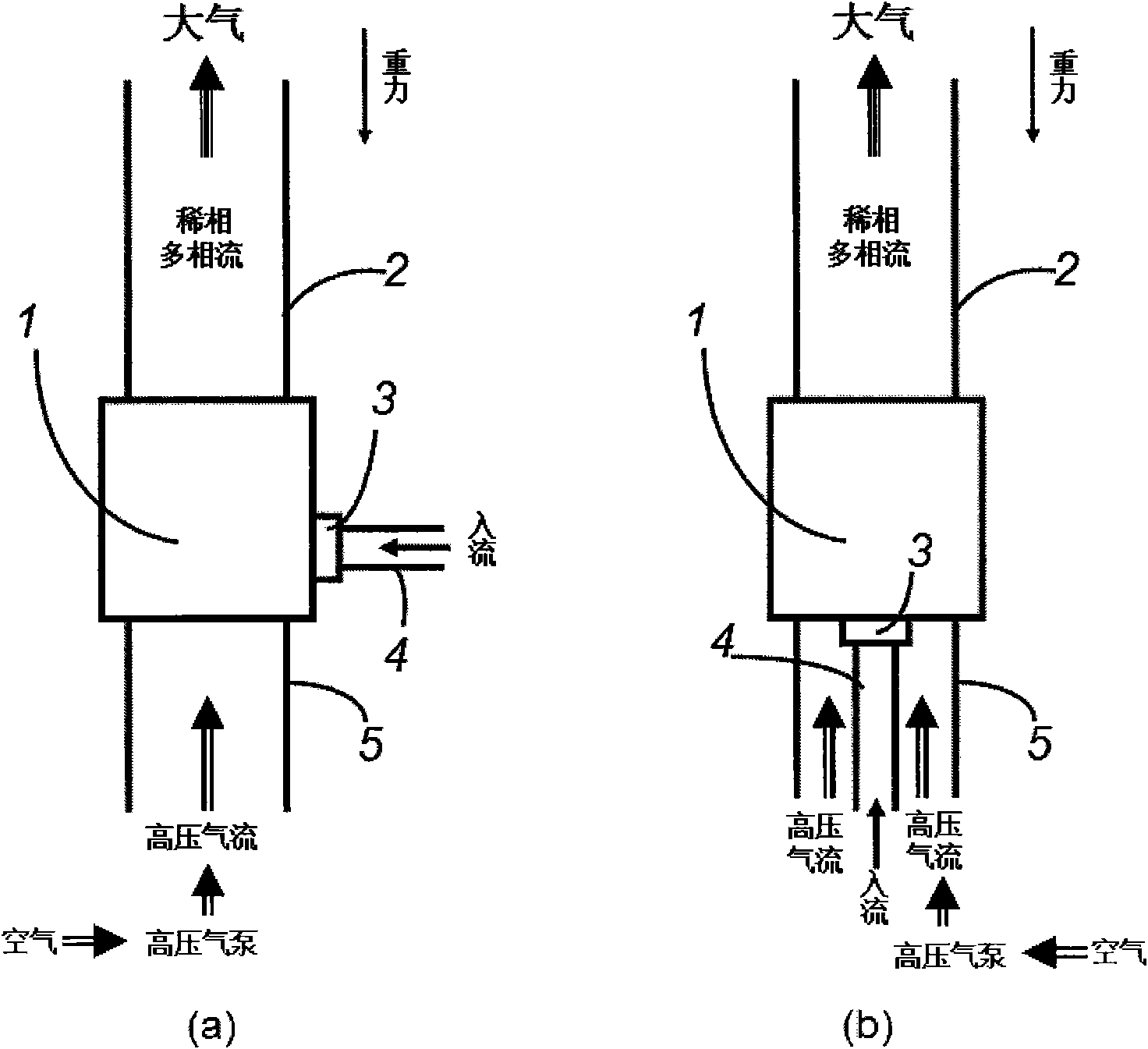
[0039] Embodiment one: see figure 1 , the anti-gravity dilute phase pneumatic conveying device of the fluid, the atomization cavity 1, the buoyancy tube 2, the atomizer 3, the inflow tube 4 and the gas inlet tube 5. The atomization chamber 1 is connected with the buoyancy tube 2 , the atomizer 3 and the gas inlet tube 5 , and the inlet tube 4 is connected with the atomizer 3 . The water flow in the inflow pipe 4 is sprayed into the atomization chamber 1 through the atomizer 3, and mixed with the high-pressure airflow entering the atomization chamber 1 from the air inlet pipe 5 to form a high-pressure steam and mist flow, and then under the action of the pressure difference , the buoyancy tube 2 transports the high-pressure steam and mist to the anti-gravity direction, and finally enters the atmosphere at the outlet of the buoyancy tube to achieve the purpose of changing the atmospheric humidity.

Embodiment 2

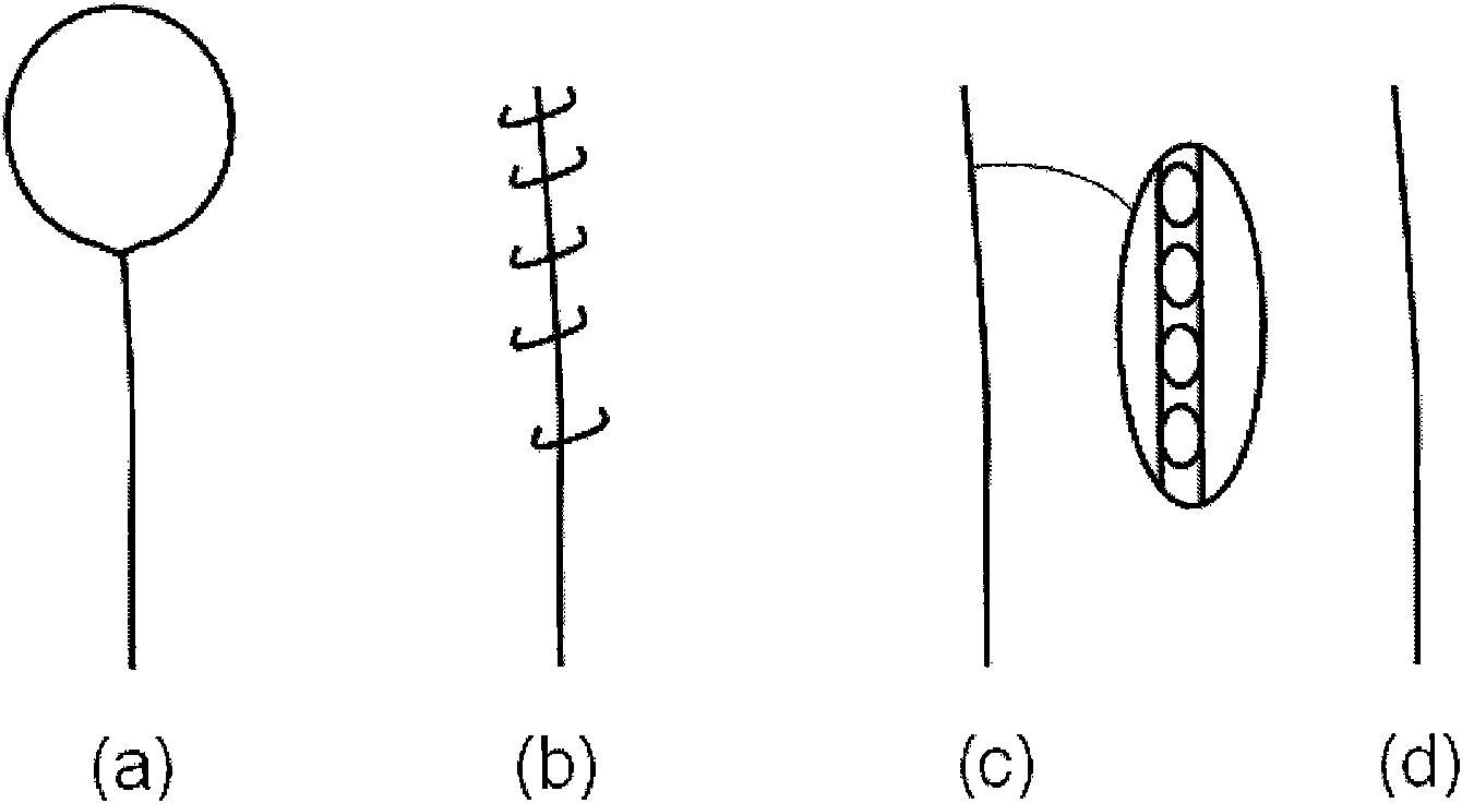
[0040] Embodiment two: see figure 1 and figure 2 , the principle of this embodiment is the same as that of Embodiment 1, and the special features are: the buoyancy tube is a pipe fitting made of light material, and there is a light balloon traction tube (a), or a kite traction tube (b), or a light air bubble film tube ( c), or homogeneous material pipe (d), the high-pressure airflow provided by external power sends atomized water or powder particles into the atmosphere.

Embodiment 3

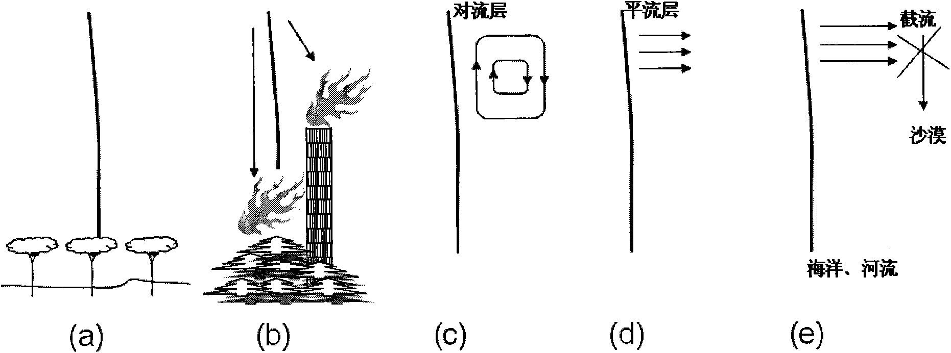
[0041] Embodiment three: see figure 1 and image 3 (a), the principle of this embodiment is the same as that of Embodiment 1, and the special feature is: the purpose of applying this device here is to irrigate a large area, so that irrigation no longer only depends on the time-consuming and labor-intensive ground engineering on the ground, and does not Complex topography needs to be considered and areas far from water sources can be irrigated.


PUM


Abstract

The invention relates to an antigravity dilute-phase pneumatic conveying device for fluid. The device comprises an atomizing cavity, a buoyancy tube, an atomizer, an inflow pipe and an air inlet pipe, wherein the atomizing cavity is connected with the buoyancy tube, the atomizer and the air inlet pipe; the inflow pipe is connected with the atomizer; water or dust in the inflow pipe is sprayed into the atomizing cavity without passing through the atomizer, and is mixed with high pressure draft which enters the atomizing cavity from the air inlet pipe to form gas-water or gas-dust dilute-phase multi-phase flow; and the dilute-phase multi-phase flow is conveyed by the buoyancy tube towards the antigravity direction under the action of pressure difference between the upper end and the lower end of the buoyancy tube, and enters into atmosphere at the outlet of the buoyancy tube finally. The invention proposes that substances, such as water or duct, on the earth are conveyed vertically to the atmosphere with different heights by a gas-water or gas-dust mixed stream mode; the atomized water conveyed to the atmosphere can be combined with original water drops in the atmosphere by impacting to form rainfall by chain effect, or stays in the atmosphere to change atmosphere humidity and lighting conditions; and the dust conveyed to the atmosphere can form condensation nucleus of water to realize artificial precipitation. The device can realize artificial regulation of rain, and can be used in the field of demisting, agricultural irrigation, fire-fighting, artificial weather and climate, desert treatment and the like.

Description

technical field [0001] The invention relates to a fluid antigravity dilute phase pneumatic conveying device. It can vertically transport surface water or solid powder particles into the atmosphere at different heights, and is used in fields such as defogging, agricultural irrigation, fire protection, artificial meteorological climate, and desert control. Background technique [0002] The invention originates from the research on spray atomization metallurgy technology, but the significance of the invention goes beyond the application of this technology itself. [0003] The core technology of spray atomization metallurgy technology is jet atomization technology. The effect of jet atomization depends on some physical parameters, such as interfacial tension, viscosity, etc., and some motion parameters such as speed difference. Among them, under the determined working medium and temperature conditions, smaller liquid particles can be obtained by increasing the speed difference ...

Claims


Application Information

Patent Timeline
Patent Type & Authority Applications(China)
IPC IPC(8): B65G53/16B65G53/34B65G53/52B65G53/60F17D1/08
Inventor 王志亮徐海丽
Owner SHANGHAI UNIV
Why Eureka
Try Eureka