Die for manufacturing glass container

A technology for glass containers and moulds, applied in glass blowing moulds, etc., can solve the problems of difficult heat dissipation, deformation, elongation and deformation of the neck and shoulders of the bottle, and achieve the effect of accelerating the cooling speed

Inactive Publication Date: 2010-11-17
CHANGSHU JIANHUA MOLD TECH
View PDF10 Cites 5 Cited by
  • Summary
  • Abstract
  • Description
  • Claims
  • Application Information

AI Technical Summary

Problems solved by technology

[0004] The above-mentioned patented technical solutions are all proposed for bottles with bottlenecks such as beer bottles and red wine bottles. It should be said that each has unique technical advantages, but there are disadvantages, because after the glass products are formed in the glass mold, the formed glass products need to be clamped with bottle tongs. The glass bottle is taken out of the mold. The higher the quality of the wine bottle, the higher the quality requirement, which is specifically reflected in the strict requirements on the consistency of the shape of the neck and shoulder.
As we all know, the thickness of the bottle mold used to form wine bottles near the neck and shoulders is thick, and the heat is difficult to dissipate quickly. Therefore, when the bottle is taken out with bottle tongs, the glass frit at the neck and shoulders of the bottle is not heated due to high temperature. Reach the degree of hardening like the bottle body, that is to say, the neck and shoulders of the bottle still have a certain degree of plasticity, so when the bottle tongs hold it, it is easy to cause the neck and shoulders of the bottle to elongate and deform due to the gravity of the bottle itself, affecting quality of the bottle
However, in the above-mentioned many patent application schemes, no technical inspiration for solving the deformation of the neck and shoulders of the bottle has been given. For this reason, the applicant has made active and beneficial explorations and found a solution to the problem. The technical scheme to be introduced below It is against this background that the

Method used


Image

  • Die for manufacturing glass container
  • Die for manufacturing glass container
  • Die for manufacturing glass container

Examples


Embodiment Construction

[0017] In order to enable the examiners of the patent office, especially the public, to understand the technical essence and beneficial effects of the present invention more clearly, the applicant will describe in detail below in conjunction with the accompanying drawings in the form of embodiments, but none of the descriptions of the embodiments is a description of the present invention. Restriction of the inventive solution, any equivalent transformation made according to the concept of the present invention which is merely formal but not substantive shall be regarded as the scope of the technical solution of the present invention.

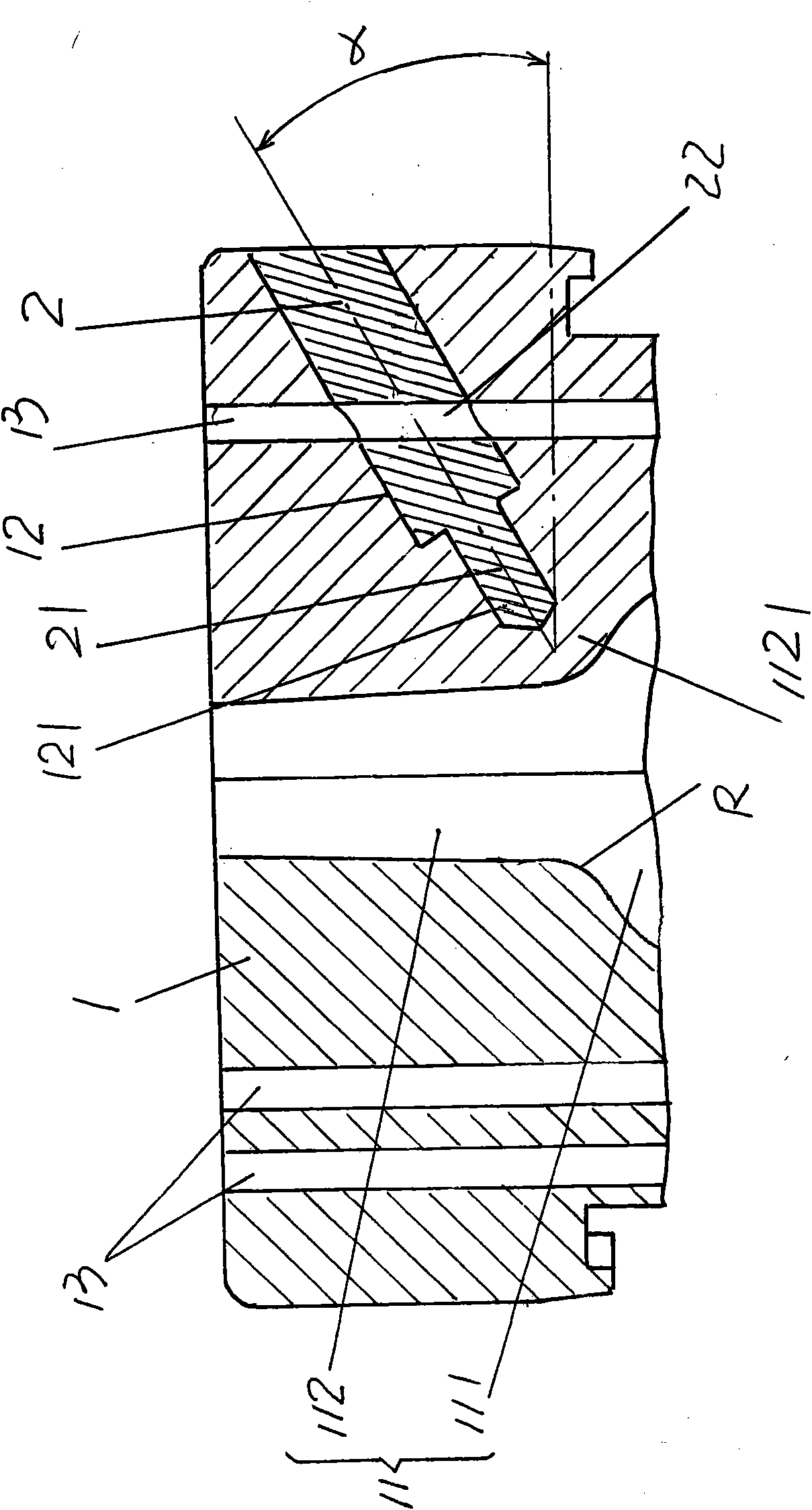
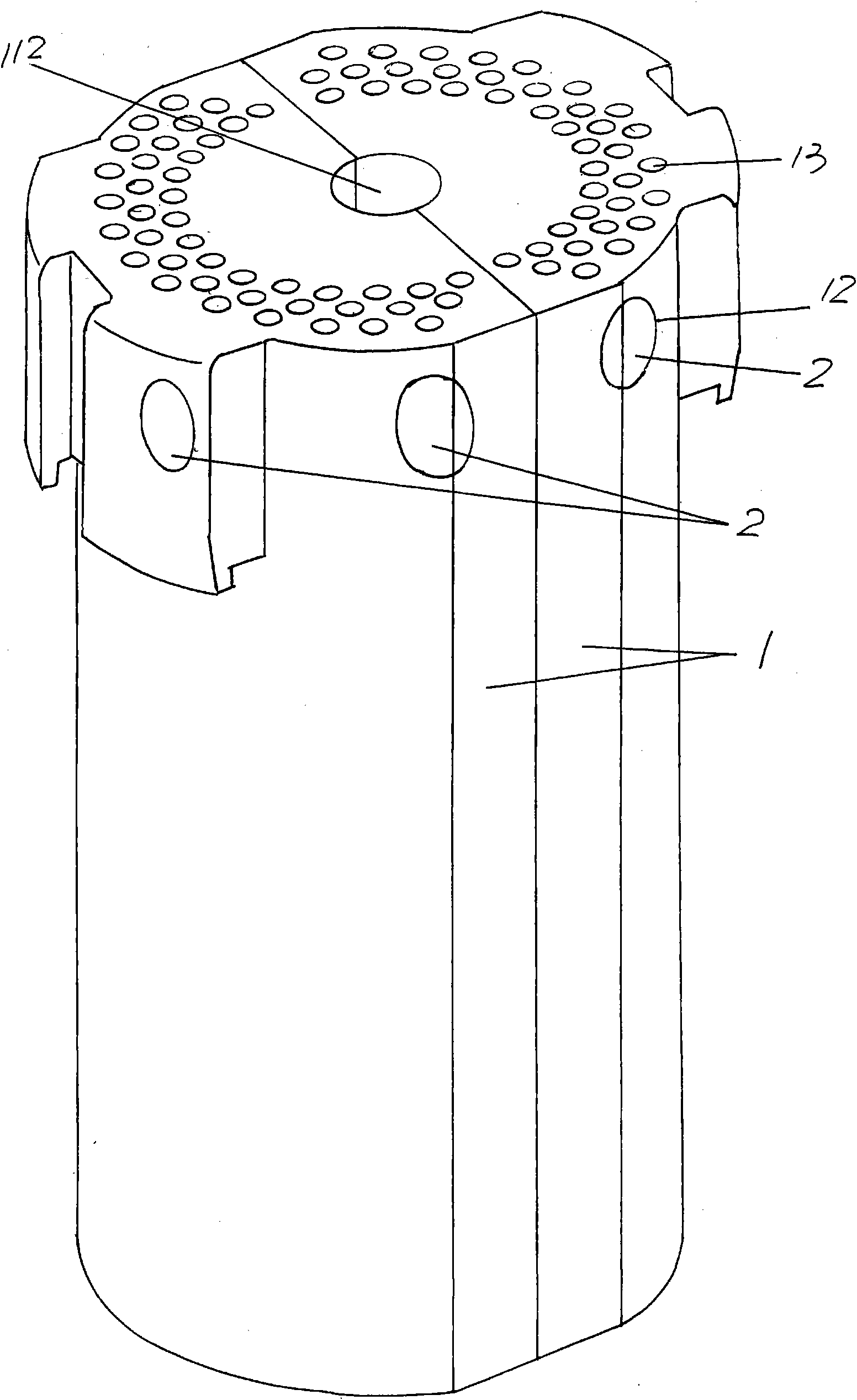
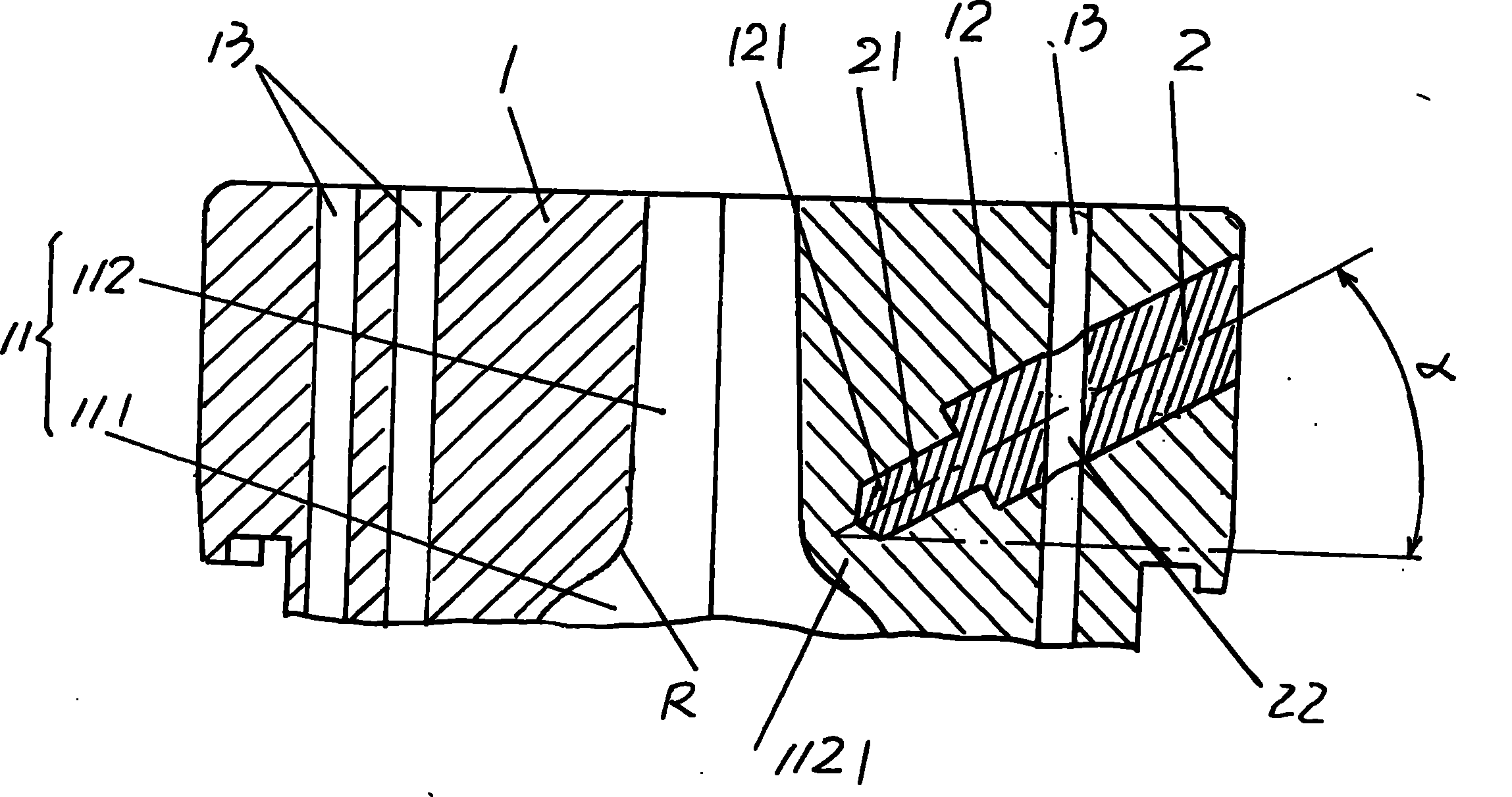
[0018] Please see figure 1 with figure 2 , a pair of bottle half-molds 1 opposite to each other in the use state with the same shape each have a bottle mold cavity 11. According to known common sense, each bottle mold cavity 11 is composed of a bottle body cavity 111 and a bottleneck cavity 112. The bottle body cavity 11 and the bottle neck ca...


PUM


Abstract

The invention relates to a die for manufacturing a glass container, and belongs to the technical field of glass dies. The die comprises a pair of bottle half-dies which have the same shapes and are arranged opposite to each other, wherein a bottle die cavity formed by a bottle body cavity and a bottleneck cavity commonly is formed on the inner wall of each bottle half-die. The die is characterized in that: heat transfer post holes are formed on upper parts of the pair of bottle half-dies and side faces surrounding the bottleneck cavities at intervals, and a heat transfer post is arranged in each heat transfer post hole. In the technical scheme, a group of heat transfer post holes are formed on the upper parts of the pair of bottle half-dies and the side faces surrounding the bottleneck cavities at intervals, and the heat transfer post is arranged in each heat transfer post hole, so the cooling speed at bottleneck shoulders can be accelerated. When bottle pincers take formed glass bottles out of the bottle die cavities of the pair of bottle half-dies, the glass bottles are not deformed, so the production requirements of demanding high-quality wine bottles can be met.

Description

technical field [0001] The invention belongs to the technical field of glass moulds, in particular to a mold for making glass containers. Background technique [0002] Glass containers such as glasses, cosmetic bottles, all kinds of pickle bottles, vases, wine bottles, beverage bottles, etc., the production of such glass bottle containers needs to rely on corresponding bottle molds. About the bottle mold that glass container is used, there is no lack of in the patent document, wherein the mold around making beer bottle and wine bottle is in the majority, typical as the mold that publication number CN101298355A recommends making glass container usefulness, this patented technical scheme is in a pair The upper part of the half-mold of the bottle and corresponding to the surrounding of the bottle neck cavity are provided with insulation holes to increase the temperature around the bottle neck cavity, so that the liquid material, that is, the glass melt, can be evenly distribute...

Claims


Application Information

Patent Timeline
Patent Type & Authority Applications(China)
IPC IPC(8): C03B9/347
Inventor 马建华朱伟国马连保晏庆宝方朝辉
Owner CHANGSHU JIANHUA MOLD TECH
Why Eureka
Try Eureka