Radical magnetic bearing with independent electromagnet structure

An electromagnet and magnetic bearing technology, applied in the field of magnetic bearings, can solve problems such as crosstalk, magnetic field distribution crosstalk, and unscientific issues, and achieve the effects of avoiding signal interference, avoiding mutual crosstalk, and flexible structure assembly

Inactive Publication Date: 2010-11-17
TSINGHUA UNIV
View PDF3 Cites 27 Cited by
  • Summary
  • Abstract
  • Description
  • Claims
  • Application Information

AI Technical Summary

Problems solved by technology

Since the distance between the front end of the magnetic pole and the root of the magnetic pole is different, in order to facilitate the installation of the winding wire package 6, the space 7 at the root of the magnetic pole is often not fully utilized
[0007] 2. There may be crosstalk between each closed magnetic circuit, especially when the coil has a fault such as inter-turn short circuit or iron strike, according to the excitation current design of the excitation coil, the closed magnetic circuit that should have been formed on the adjacent magnetic pole is formed by other magnetic poles. Closed, since the control system still controls the current according to the logic of normal working conditions, the magnetic field distribution on each magnetic pole will have uncertain crosstalk, which is not conducive to fault diagnosis and maintenance
[0008] 3. When the magnetic bearing has a mechanical failure and requires maintenance or replacement of the stator components, even if only one of the magnetic poles has a problem, it has to be replaced as a whole, resulting in waste and increased maintenance costs
[0009] 4. Sometimes the radial magnetic bearings have different forces in each direction. For example, when the rotor is designed horizontally, that is, when the rotor axis is arranged horizontally, the electromagnet at the upper end of the magnetic bearing bears the weight of the rotor additionally than the electromagnet at the lower end. In fact, the electromagnet at the lower end hardly needs to provide any carrying capacity, and the traditional completely axisymmetric magnetic bearing design is obviously unscientific

Method used


Image

  • Radical magnetic bearing with independent electromagnet structure
  • Radical magnetic bearing with independent electromagnet structure
  • Radical magnetic bearing with independent electromagnet structure

Examples


Embodiment Construction

[0039] The specific implementation manners of the present invention will be further described in detail below in conjunction with the accompanying drawings and embodiments. The following examples are used to illustrate the present invention, but are not intended to limit the scope of the present invention.

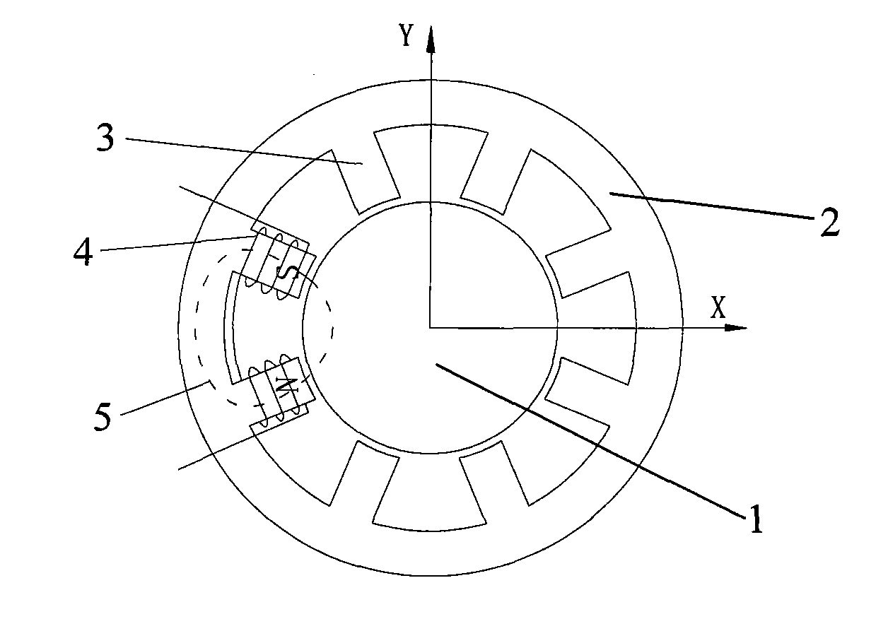
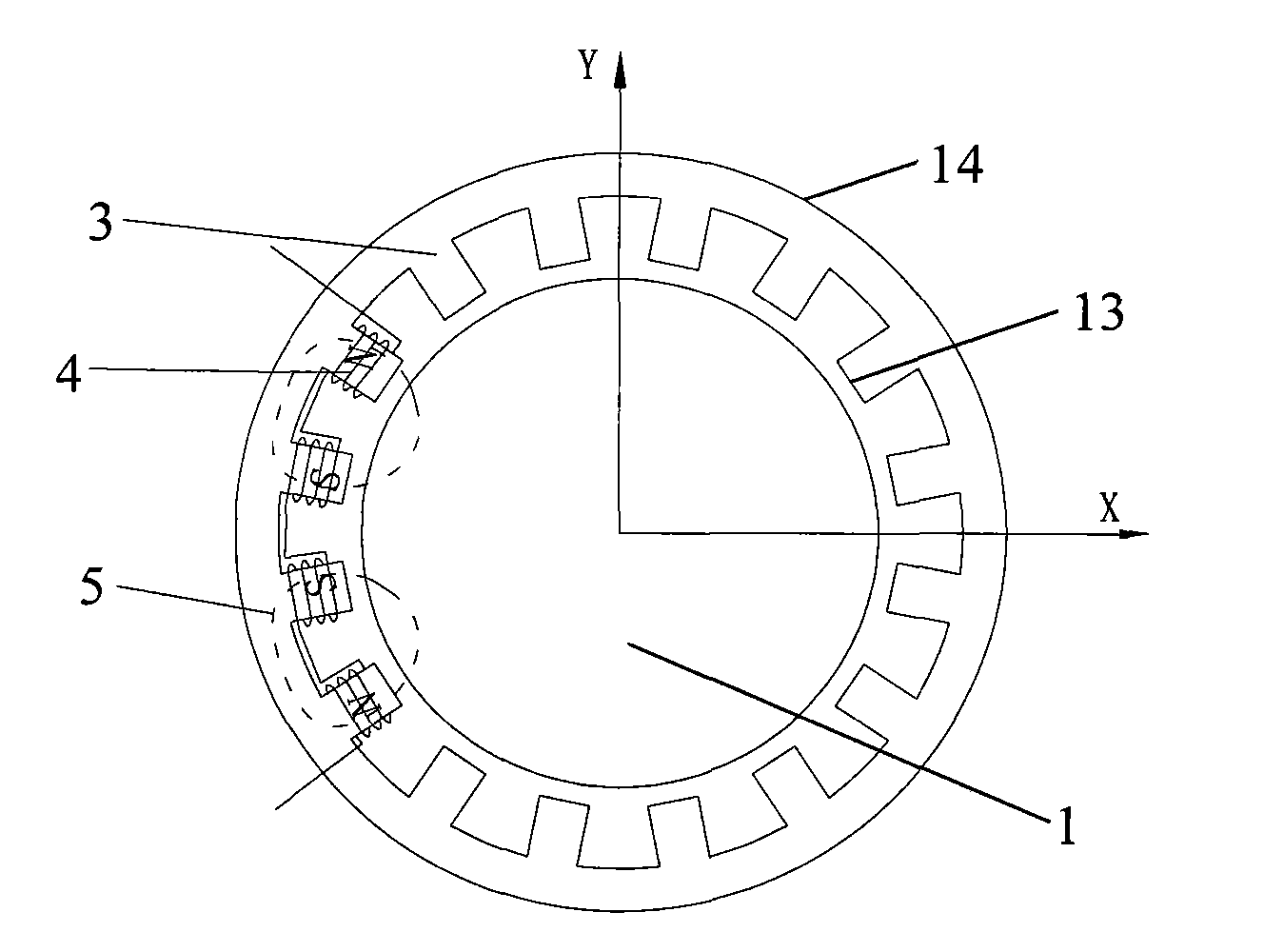
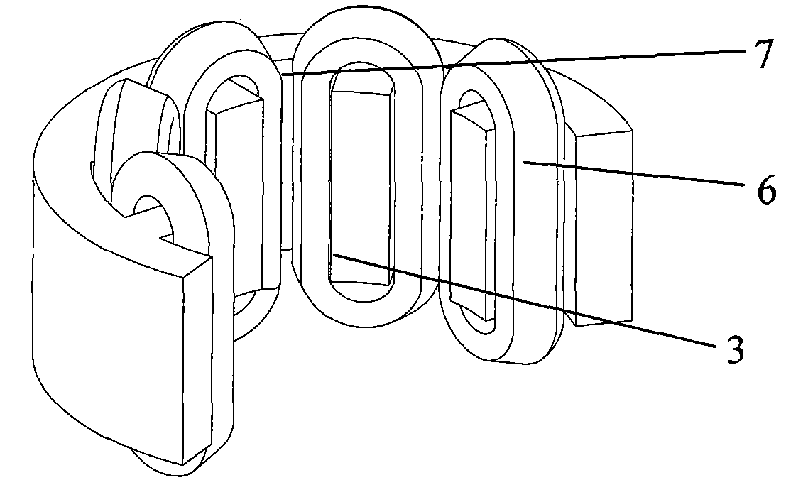
[0040] Figure 4 is a schematic structural view of an independent electromagnet unit in an embodiment of the present invention; Figure 5 It is a schematic diagram of a magnetic bearing with an independent electromagnet according to an embodiment of the present invention; Figure 6 is a side sectional view of a magnetic bearing with an independent electromagnet according to an embodiment of the present invention; Figure 7 It is a schematic diagram of the asymmetric magnetic bearing structure of the embodiment of the present invention.

[0041] The present invention provides the most basic U-shaped independent electromagnet unit that can form a closed magnetic circuit w...


PUM


Abstract

The invention discloses a radical magnetic bearing with independent electromagnet structure, comprising a rotor and a stator arranged at the periphery of the rotor; wherein the stator comprises a case and a plurality of independent electromagnets, and a plurality of electromagnets are arranged on the case at intervals. The invention has flexible structure assembly, stator semi-open type structure can be realized according to the requirement; the electromagnets are mutually independent, interference of magnetic paths between magnetic poles can be effectively avoided, and signal interference between a magnetic pole and a sensor can be avoided, thus being beneficial to improving the reliability of system; each independent electromagnet can be directly used for winding inserting, thus no additional processing mould is required to be added and no special inserting process is required to be designed; independent structure unit is easy to realize, and serialized and standardized parts can be formed, thus costs for maintenance and replacing equipment parts are all greatly reduced.

Description

technical field [0001] The invention relates to a magnetic bearing, in particular to a radial magnetic bearing with an independent electromagnet structure. Background technique [0002] Generally, according to the direction in which the magnetic bearing exerts force on the rotor, magnetic bearings are divided into two categories: radial magnetic bearings and axial magnetic bearings. The radial bearing is divided into two parts, the stator and the rotor, among which the most commonly used stator part is the 8-pole structure, such as figure 1 shown. The 8-pole radial magnetic bearing stator is divided into 4 electromagnets with closed magnetic circuits, each electromagnet controls the magnitude of the electromagnetic force applied to the rotor in a single direction; while the combination of the two opposite electromagnets can control its position The magnitude of the electromagnetic force in the positive and negative directions of the degree of freedom; further, the combinat...

Claims


Application Information

Patent Timeline
Patent Type & Authority Applications(China)
IPC IPC(8): F16C32/04H01F7/06
CPCF16C32/0461F16C32/048
Inventor 徐旸杨国军符晓明于溯源赵雷刁兴中张佑杰时振刚
Owner TSINGHUA UNIV
Why Eureka
Try Eureka