
Single screw compressor

A single-screw compressor and screw technology, which is applied in the direction of mechanical equipment, machines/engines, liquid fuel engines, etc., can solve the problems of single-screw compressor efficiency reduction, screw rotor and gate gap, etc., to reduce losses and reduce friction Loss, the effect of improving efficiency

Inactive Publication Date: 2010-11-17
DAIKIN IND LTD
View PDF1 Cites 4 Cited by
  • Summary
  • Abstract
  • Description
  • Claims
  • Application Information

AI Technical Summary

Problems solved by technology

As a result, the gap between the screw rotor and the gate is too large near the end of the suction side of the screw rotor, and the amount of gas leaking from the gap between the two is too large, which may lead to a decrease in the efficiency of the single screw compressor.

Method used


Image

  • Single screw compressor
  • Single screw compressor
  • Single screw compressor

Examples


Embodiment Construction

[0042] Hereinafter, embodiments of the present invention will be described in detail based on the drawings.

[0043] The single-screw compressor (1) (hereinafter, simply referred to as a screw compressor) of the present embodiment is installed in a refrigerant circuit that performs a refrigeration cycle to compress a refrigerant.

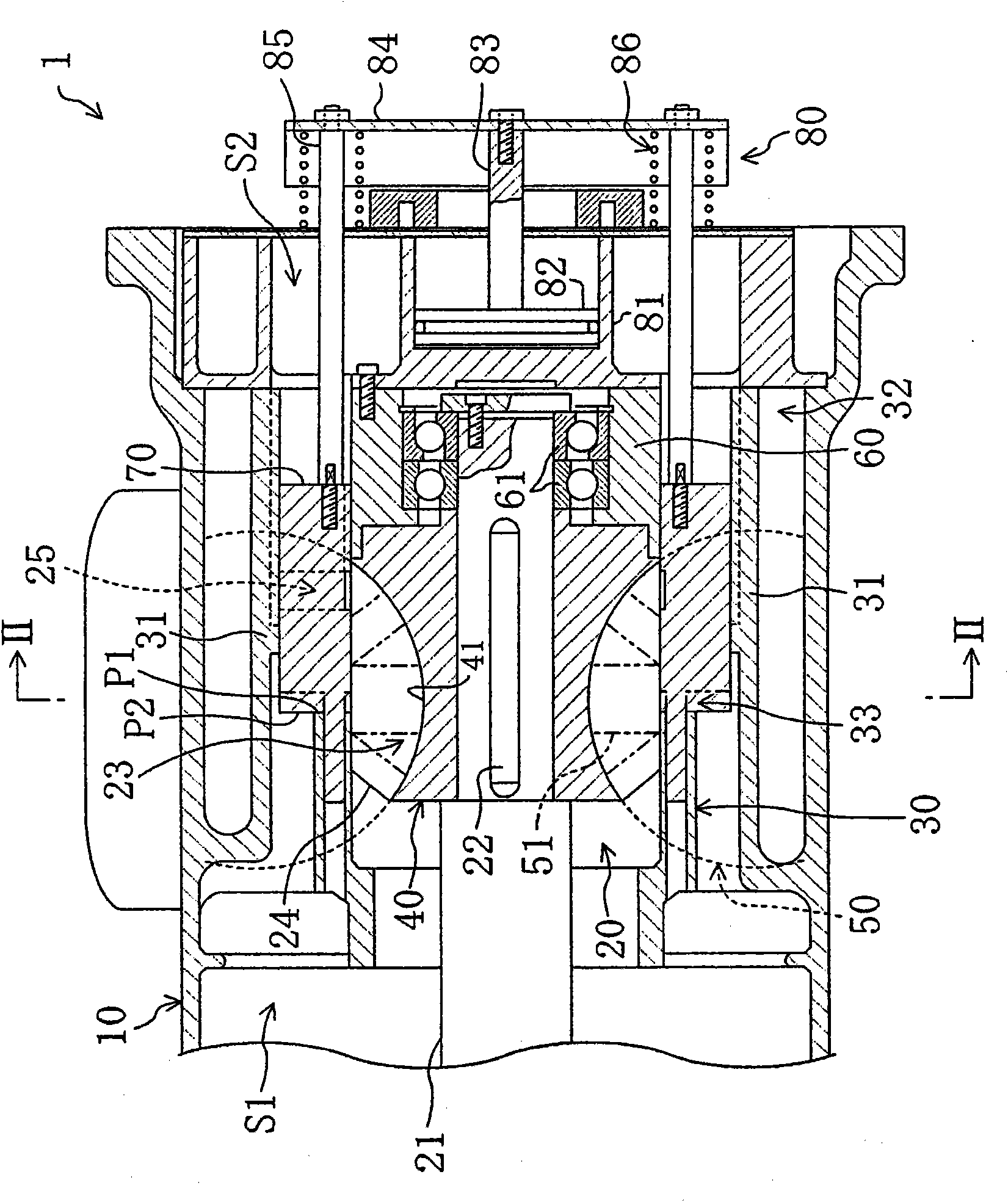
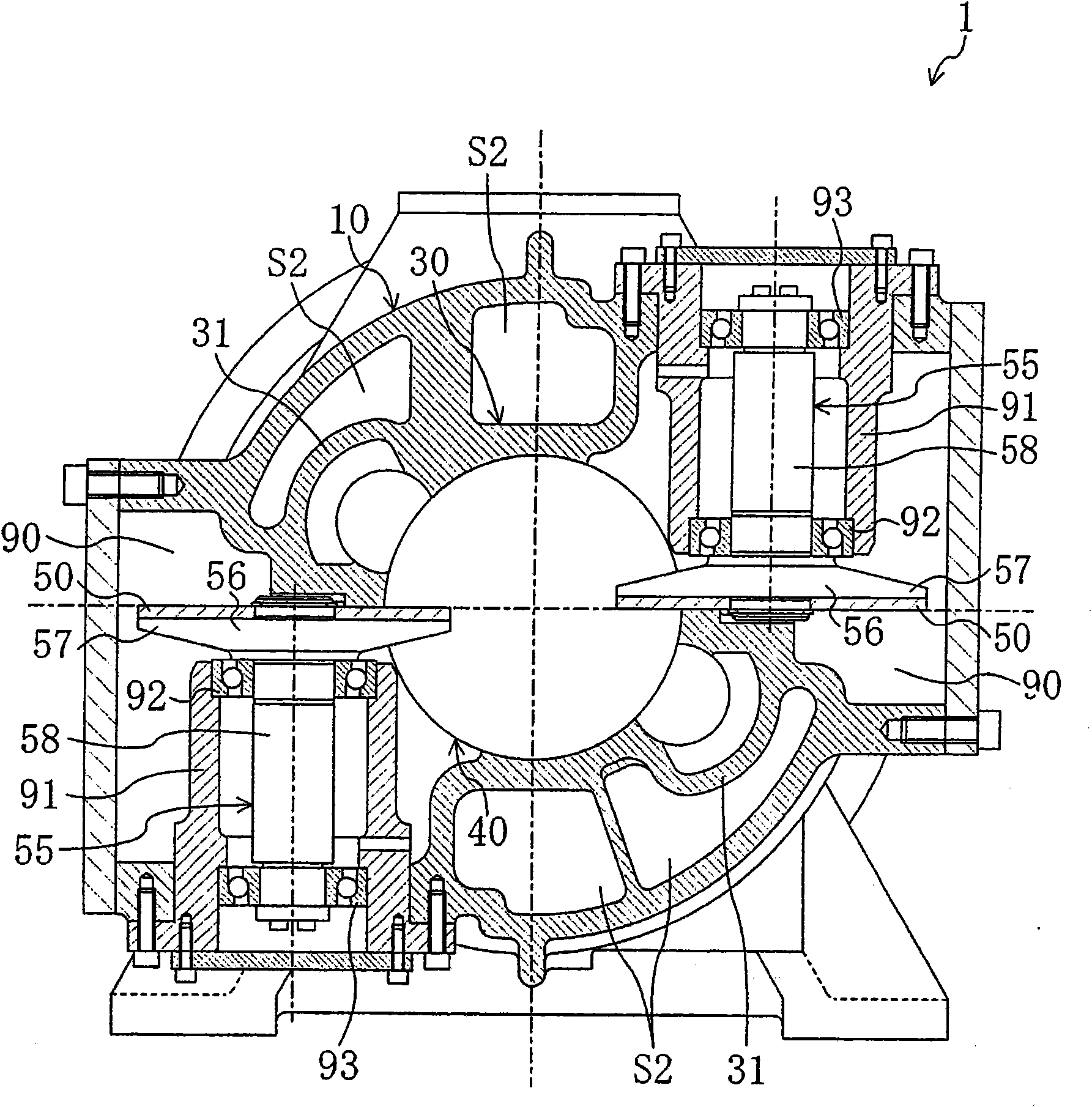
[0044] Such as figure 1 , figure 2 As shown, the screw compressor (1) constitutes a semi-hermetic type. In this screw compressor (1), a compression mechanism (20) and an electric motor for driving it are housed in one casing (10). The compression mechanism (20) is connected with the motor through a drive shaft (21). In Figure (1), the motor is omitted. In addition, the casing (10) is divided into a low-pressure space (S1) that introduces low-pressure gas refrigerant from the evaporator of the refrigerant circuit and introduces the low-pressure gas into the compression space (20), and discharges the inflow from the compression mechanism (20). T...


PUM


Abstract

A single screw compressor in which gates (51) of gate rotors (50) are engaged with helical grooves (41) of a screw rotor (40). In each helical groove (41) of the screw rotor (40), the region from the start point of the groove (41) to the middle of a compression stroke is a suction side portion (45) and the remaining region (region to the end point) is a discharge side portion (46). In the suction side portion (45), the clearance between each gate (51) and wall surfaces (42, 43, 44) of the suction side portion (45) is substantially zero. The clearance between each gate (51) and wall surfaces (42, 43, 44) of the discharge-side portion (46) is greater than the clearance between the gate (51) and the wall surfaces (42, 43, 44) of the suction side portion (45) and gradually expands toward the end points of the helical grooves (41).

Description

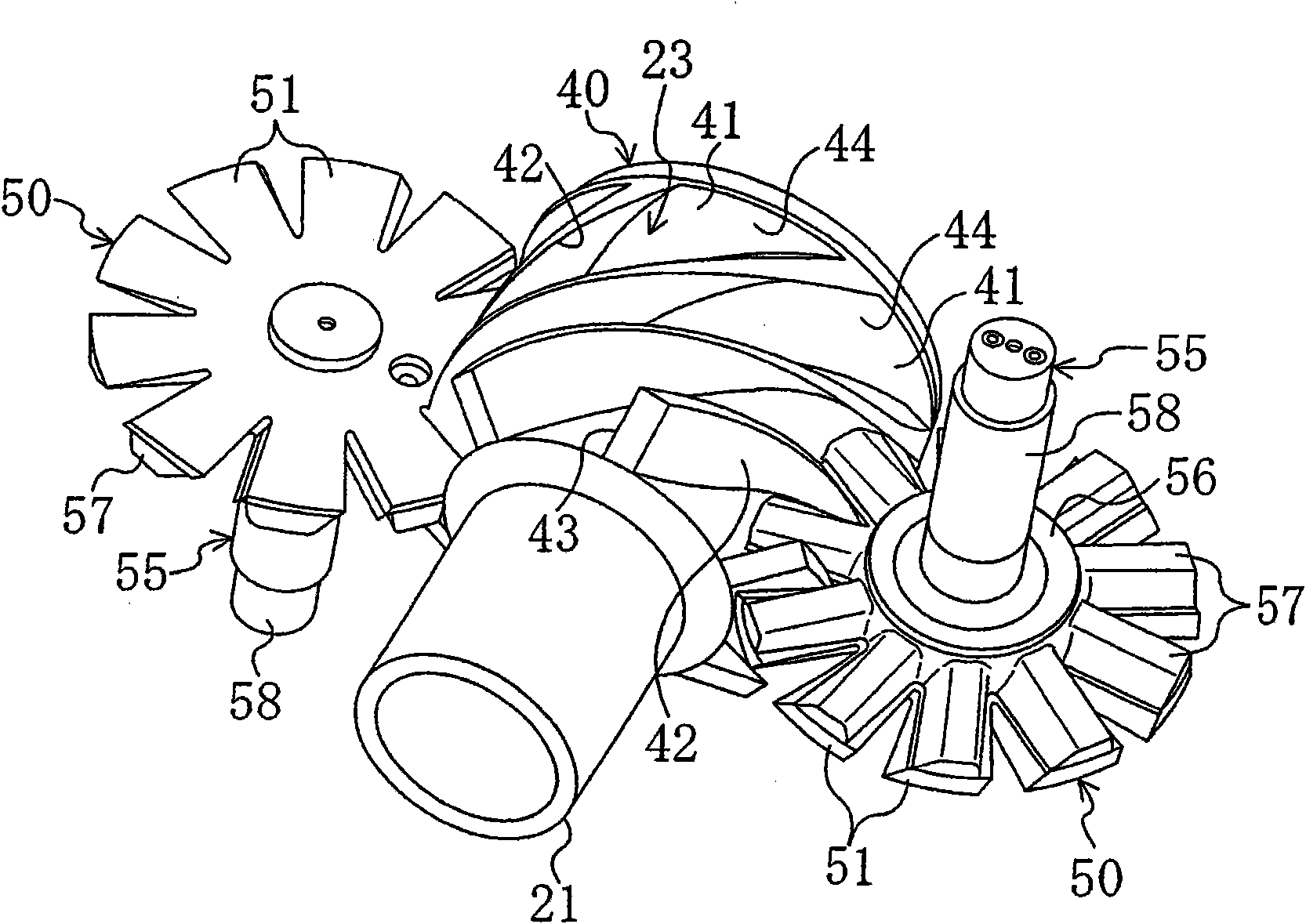
technical field [0001] The present invention relates to a method of increasing the efficiency of a single screw compressor. Background technique [0002] Conventionally, a single-screw compressor is used as a compressor for compressing refrigerant and air. For example, Patent Document 1 discloses a single screw compressor having one screw rotor and two gate rotors. [0003] This single screw compressor will be described. The screw rotor is roughly formed in a cylindrical shape, and a plurality of spiral grooves are formed on its outer periphery. The gate rotor is formed approximately in the shape of a flat plate, and is disposed on the side of the screw rotor. A plurality of rectangular plate-shaped gates are arranged radially on the gate rotor. The gate rotor is provided with a rotation axis perpendicular to the rotation axis of the screw rotor, and the gate meshes with the helical groove of the screw rotor. [0004] In this single-screw compressor, the screw rotor and...

Claims


Application Information

Patent Timeline
Patent Type & Authority Applications(China)
IPC IPC(8): F04C18/52
CPCF04C18/52F04C2270/17
Inventor 室野孝义大塚要上野广道
Owner DAIKIN IND LTD
Learn More