
Method for recycling blast furnace gas

A blast furnace gas separation and recovery technology, applied in the field of blast furnace gas recovery and utilization, can solve the problems of low added value of blast furnace gas, poor utilization effect, inability to fully utilize the advantages of blast furnace gas composition and chemical properties, etc., and achieve high energy utilization rate , the effect of good use effect and high added value

Inactive Publication Date: 2010-11-24
HEILONGJIANG JIANLONG IRON & STEEL
View PDF0 Cites 11 Cited by
  • Summary
  • Abstract
  • Description
  • Claims
  • Application Information

AI Technical Summary

Problems solved by technology

[0004] The purpose of the present invention is to solve the problem that the existing blast furnace gas recycling method can not give full play to the advantages of blast furnace gas composition and chemical properties, resulting in low added value and poor utilization effect of blast furnace gas. blast furnace gas method

Method used


Image

  • Method for recycling blast furnace gas

Examples


specific Embodiment approach 1

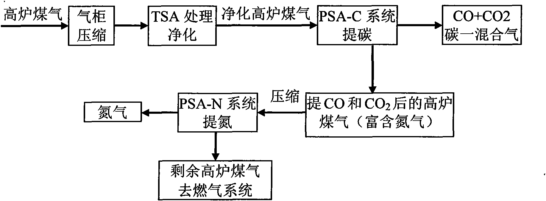
[0011] Embodiment 1: The method for recycling blast furnace gas in this embodiment is realized through the following steps: 1. Pass the blast furnace gas into the gas holder, then compress the blast furnace gas in the gas holder to a pressure of 0.01-0.1 MPa, and then Pass the blast furnace gas into the temperature swing adsorption system (TSA) for processing, control the inlet temperature of the temperature swing adsorption to be 300-400°C, and the outlet temperature to be 170-200°C to obtain purified blast furnace gas; 2. Add the purified blast furnace gas obtained in step 1 to After the pressure reaches 0.2-5MPa, it is sent to the pressure swing adsorption carbon extraction system (PSA-C) to adsorb and purify the carbon-mixture gas. Under the condition of gauge pressure of -0.1MPa~0.15MPa, desorb for 1min~10min to obtain CO and CO with a volume purity of more than 95%. 2 3. Pressurize the remaining blast furnace gas discharged from the gas outlet of the pressure swing adsor...

specific Embodiment approach 2

[0015] Embodiment 2: This embodiment differs from Embodiment 1 in that in step 1, the blast furnace gas in the gas tank is compressed to a pressure of 0.03-0.08 MPa. Other steps and parameters are the same as those in Embodiment 1.

specific Embodiment approach 3

[0016] Embodiment 3: The difference between this embodiment and Embodiment 1 is that in step 1, the blast furnace gas in the gas holder is compressed to a pressure of 0.06 MPa. Other steps and parameters are the same as those in Embodiment 1.


PUM


Abstract

The invention relates to a method for recycling blast furnace gas, and solves the problems of low additional value and poor using effect of the blast furnace gas because the advantages of the composition and chemical properties of the blast furnace gas cannot be brought into full play in the conventional method for recycling the blast furnace gas. The method comprises the following steps of: firstly, compressing the blast furnace gas and then allowing the compressed blast furnace gas to enter a temperature swing adsorption system for treatment to obtain purified blast furnace gas; secondly, pressurizing the purified blast furnace gas and then conveying the pressurized blast furnace gas to a pressure swing adsorption carbon extraction system for adsorption and purification to obtain carbon mixed gas; thirdly, pressurizing the rest blast furnace gas and then conveying the pressurized blast furnace gas to a pressure swing adsorption nitrogen extraction system to separate and recycle nitrogen; and finally, returning the rest blast furnace gas to a gas fuel system. The volume purity of the CO and CO2 mixed gas is over 95 percent and the mixed gas provides a synthesis air source for methanol and an organic synthesis and processing system; the volume purity of the nitrogen is over 99.5 percent, so that the problem that steel enterprises need the nitrogen with the volume purity of over 99 percent is solved; and the blast furnace gas has high additional value.

Description

technical field [0001] The invention relates to a method for recycling blast furnace gas. Background technique [0002] In iron and steel enterprises, blast furnace gas is a by-product produced in the ironmaking process, and its main components are: CO, CO 2 , N 2 、H 2 etc., in which the content of combustible components CO accounts for about 27%, H 2 The content of CO is about 2.7%. 2 , N 2 The contents accounted for 15%, 55% respectively, CH 4 Accounting for about 0.3%, the calorific value is low. Modern ironmaking production generally adopts large volume, high blast temperature, high smelting intensity, and high coal powder injection production technology. The use of these advanced production technologies improves labor productivity and reduces energy consumption, but the calorific value of the blast furnace gas produced Lower, increasing the difficulty of use. CO in blast furnace gas 2 , N 2 It does not participate in combustion to generate heat, nor can it sup...

Claims


Application Information

Patent Timeline
Patent Type & Authority Applications(China)
IPC IPC(8): C21B5/06
Inventor 张志祥张玉才杨宪礼吴恒奎安丰森刘建勋
Owner HEILONGJIANG JIANLONG IRON & STEEL
Learn More