Multi-functional integrated type hydraulic cylinder

An integrated, hydraulic cylinder technology, applied in the direction of fluid pressure actuators, etc., can solve the problems of low response frequency, complex hydraulic system, mechanical installation, etc., achieve fast cycle speed, expand the scope of application, and improve power density Effect

Active Publication Date: 2012-09-26
泸州众大科技液压件有限公司
View PDF0 Cites 0 Cited by
  • Summary
  • Abstract
  • Description
  • Claims
  • Application Information

AI Technical Summary

Problems solved by technology

[0003] (1) Combined configuration of multiple single-stage or multi-stage piston cylinders, each cylinder is responsible for different functions, and coordination needs to be considered when returning quickly; its disadvantages are bulky, complex structure, inconvenient pipeline layout, low response frequency, and many Machinery cannot be installed due to space constraints
[0004] (2) Combination of two single-stage or multi-stage piston cylinders, one cylinder is used for fast positioning function; the other cylinder is responsible for fast forward and work forward functions, but the hydraulic system needs to be equipped with low-pressure, large-flow, high-pressure quantitative system The oil source of the hydraulic pump with small and medium flow or automatic variable, and the oil source is set separately for the oil cylinder with the positioning function, because the required flow is quite different from the main oil source
Its disadvantages are: even if an automatic variable oil source is used, the hydraulic pump must be considered from the maximum required flow rate, resulting in large volume, inconvenient installation and layout, relatively complicated hydraulic system, and large power loss
Its disadvantages are: high cost, large volume, inconvenient installation and layout, relatively complicated hydraulic system, and it is necessary to consider replenishing oil for the accumulator in the system

Method used


Image

  • Multi-functional integrated type hydraulic cylinder
  • Multi-functional integrated type hydraulic cylinder
  • Multi-functional integrated type hydraulic cylinder

Examples


Embodiment Construction

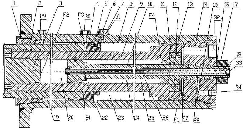
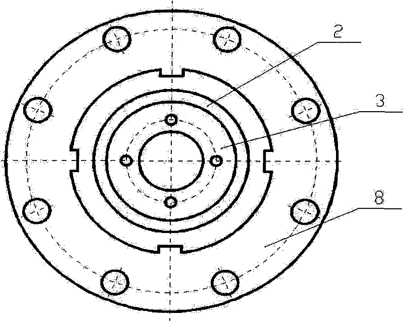
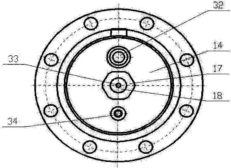
[0029] See figure 1 figure 2 with image 3 The multifunctional integrated hydraulic cylinder shown includes a master cylinder head 14 fitted and connected to the right end of the master cylinder 8, a cylindrical master cylinder piston rod 9, which is arranged in the master cylinder and whose right end is matched with the master cylinder. The quick cylinder guide sleeve 11 arranged in the right end of the cylindrical master cylinder piston rod 9 is matched with the middle of the cylindrical master cylinder piston rod and fixedly connected to the spacer ring 4 in the middle of the master cylinder. The three-petal snap key 5 connected by the isolation ring, the master cylinder guide sleeve 2 whose inner wall matches the left part of the cylindrical master cylinder piston rod and the right end matches the inner wall of the master cylinder;

[0030] The main cylinder 8 is provided with a first oil port 29, a second oil port 30 and a third oil port 31, and the main cylinder head 14 is...


PUM


Abstract

The invention discloses a multi-functional integrated type hydraulic cylinder. The multi-functional integrated type hydraulic cylinder comprises a main cylinder barrel, a main cylinder cover, a barrel-shaped main cylinder piston rod, a rapid cylinder guide sleeve, an isolating ring, a three-section card key and a main cylinder guide sleeve and is characterized in that: a first oil port, a second oil port and a third oil port are formed on the main cylinder barrel; a fourth oil port and a sixth oil port are formed on the main cylinder cover; a positioning cylinder guide sleeve is matched with the inner wall of the left end part of the main cylinder barrel; the inner wall of the positioning cylinder guide sleeve is matched with the outer wall of the main cylinder guide sleeve; the left end part of a barrel-shaped rapid cylinder piston rod is matched with the inner wall of the barrel-shaped main cylinder piston rod; the right end of the barrel-shaped rapid cylinder piston rod is connected with a locknut in a matching way; a rapid cylinder head is connected with the inner wall of the left end part of the barrel-shaped main cylinder piston rod in a matching way; a low-pressure oil inlet pipe is fixedly connected in the barrel-shaped rapid cylinder piston rod; and the right end of the low-pressure oil inlet pipe is a fifth oil port. The multi-functional integrated type hydraulic cylinder has the advantages of compact structure, high circulating operation speed, high working pressure, large thrust force of a working condition, high power density and convenient installation.

Description

Technical field [0001] The invention belongs to a hydraulic actuator, and in particular relates to a multifunctional integrated hydraulic cylinder. Background technique [0002] At present, the structural design of hydraulic cylinders for linear motion at home and abroad includes single-stage, multi-stage plunger type, single-stage, multi-stage piston type, and two-way thrust type. It is necessary to realize the multiple functions of hydraulic cylinders such as rapid positioning of low pressure and flow, rapid work advancement of low pressure and flow, high pressure and flow rate, low speed and large thrust work advancement, and low pressure and flow rate rapid return. According to the difference of pressure, flow and control methods, basically adopt The following way: [0003] (1) Multiple single-stage or multi-stage piston cylinders are configured, each cylinder has different functions, and coordination needs to be considered when returning quickly; its disadvantages are bulky, ...

Claims


Application Information

Patent Timeline
Patent Type & Authority Patents(China)
IPC IPC(8): F15B15/16
Inventor 陈启松徐光德
Owner 泸州众大科技液压件有限公司
Why Eureka
Try Eureka