Regeneration method of charging roller of laser imaging processing box

A technology of laser imaging and charging roller, which is applied in optics, electrical recording, instruments, etc., can solve the problems of bottom dust, influence on insulation performance, and decline in conductivity, and achieve simple and easy process steps, recovery of conductivity, and excellent quality Effect

Active Publication Date: 2012-09-05
PRINT RITE UNICORN IMAGE PROD CO LTD
View PDF0 Cites 0 Cited by
  • Summary
  • Abstract
  • Description
  • Claims
  • Application Information

AI Technical Summary

Problems solved by technology

After the aforementioned charging roller 100 or charging roller 200 is used for one working cycle or several working cycles, the conductive layer 104 or conductive layer 203 usually has obvious cracks and holes due to wear, or the electrical conductivity drops sharply, so that When the image is printed, there will be black blocks and black stripes on the manuscript surface. In addition, the insulating layer 102 or insulating layer 202 will be filled with a part of carbon powder accordingly, which will affect its insulating performance, or due to the filling of the insulating layer 102 or insulating layer 202. The toner of layer 202 diffuses to the surroundings, resulting in bottom dust on the manuscript surface when printing images

Method used


Image

  • Regeneration method of charging roller of laser imaging processing box
  • Regeneration method of charging roller of laser imaging processing box
  • Regeneration method of charging roller of laser imaging processing box

Examples


Embodiment Construction

[0025] The charging roller regeneration method of the laser imaging process box of the present invention will be described in detail below in conjunction with the accompanying drawings.

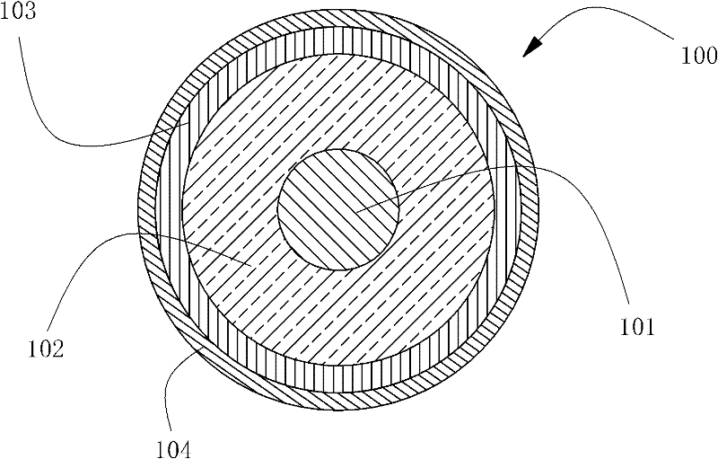
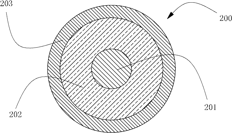
[0026] see figure 2 , 3 , respectively show the cross-sectional views of two charging rollers of the laser imaging process cartridge suitable for the regeneration method of the present invention.

[0027] figure 2 The illustrated cross-sectional structure of the charging roller 100 includes a metal mandrel 101 , an insulating layer 102 , a transition layer 103 and a conductive layer 104 . image 3 The illustrated cross-sectional structure of the charging roller 200 includes a metal mandrel 201 , an insulating layer 202 and a conductive layer 203 . The insulating layer 102 or the insulating layer 202 of the two charging rollers generally use foamed sponge as a raw material. Both the conductive layer 104 and the conductive layer 203 of the two charging rollers are usually made of conducti...


PUM


Abstract

The invention relates to a regeneration method of a charging roller of a laser imaging processing box, wherein the charging roller works for at least one work period. The cross section structure of the charging roller at least comprises a mandrel, an insulating layer coated on the mandrel and a conducting layer coated on the insulating layer. The regeneration method comprises the following processing steps in sequence: (1) removing the coatings on the periphery surface of the insulating layer; (2) using high-pressure airflow to wash the insulating layer through blowing, wherein the high-pressure airflow dispersedly flows past pores of the insulating layer; and (3) coating original functional layers at least comprising a new conductive layer, wherein the periphery surface of the new conductive layer is exposed. The method is simple and practicable, has the characteristics of high efficiency and low cost, and can be used for effectively recovering the conductivity of the conductive roller and simultaneously eliminating bottom ash which occurs on a work surface and is caused by the charging roller when the image is printed, thus the reproduced product has favorable quality.

Description

technical field [0001] The invention relates to a regeneration method of a charging roller of a laser imaging processing box. The processing box includes a photosensitive drum, a charging roller, a developing roller, a powder feeding roller, a powder outlet knife, a powder mixing roller, a powder feeding frame, and a toner bin. The electrostatic latent image area laid on the surface of the photosensitive drum converts the electrostatic latent image into a visible image displayed by a developer such as toner. Background technique [0002] Image forming devices generally include various models such as copiers, laser printers, facsimile machines, ribbon printers, and LED printers. [0003] In the image forming device in the form of laser scanning or laser phototypesetting, toner is the final imaging medium to realize the transformation of image ~ ~ light ~ ~ electricity ~ ~ image. The developer roller is located near the photosensitive drum so that the toner forms an image on...

Claims


Application Information

Patent Timeline
Patent Type & Authority Patents(China)
IPC IPC(8): G03G21/18
Inventor 谢艳邓春华
Owner PRINT RITE UNICORN IMAGE PROD CO LTD
Why Eureka
Try Eureka