Photovoltaic array component with fault detecting device

A fault detection, photovoltaic array technology, applied in the monitoring of photovoltaic power generation, photovoltaic modules, photovoltaic systems, etc., can solve the problems of poor timeliness, high cost of thermal imagers, long time for temperature changes, etc., to achieve long service life, Low cost, quick response effect

Inactive Publication Date: 2010-11-24
青岛日月科技发展有限公司
View PDF6 Cites 13 Cited by
  • Summary
  • Abstract
  • Description
  • Claims
  • Application Information

AI Technical Summary

Problems solved by technology

It takes a certain amount of time from the Joule heat formed by the current to the Joule heat that causes the temperature of the component to change, because the location of the faulty component is realized by observing the thermal image, so the timeliness of this detection technology is poor
[0006] 2. For photovoltaic modules equipped with bypass diodes, even if there is a failure, its flow capacity will not drop much, so the time from the appearance of Joule heat to the formation of temperature changes is longer, that is, the timeliness is worse
[0007] 3. The cost of thermal imager is high

Method used


Image

  • Photovoltaic array component with fault detecting device
  • Photovoltaic array component with fault detecting device
  • Photovoltaic array component with fault detecting device

Examples


Embodiment 1

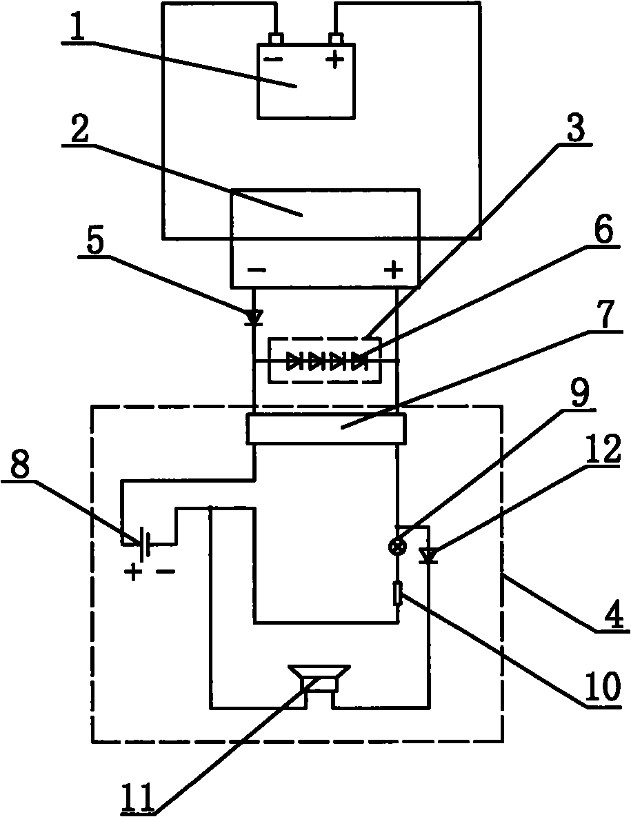
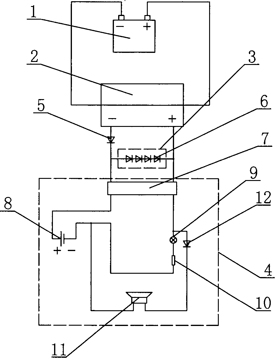
[0031] like figure 1 As shown, a photovoltaic array assembly with a fault detection device, the photovoltaic array assembly with a fault detection device includes a bypass diode group 3, a fault detection device 4, a storage battery 1 and a photovoltaic assembly 2, the The photovoltaic module 2 is connected in series with the storage battery 1; the bypass diode group 3 is connected in series with a diode 5, and the circuit composed of the bypass diode group 3 and a diode 5 connected in series is connected in parallel with the photovoltaic module 2 The fault detection device 4 is connected in parallel with the bypass diode group 3 .

[0032] The bypass diode group 3 includes four diodes 6 .

[0033] Described fault detection device 4 comprises voltage type relay 7, external power supply 8, light alarm 9, protective resistor 10 and sound alarm 11, and described light alarm 9 is LED indicator light, and described sound alarm 11 is buzzer; the voltage-type relay 7, the external ...

Embodiment 2

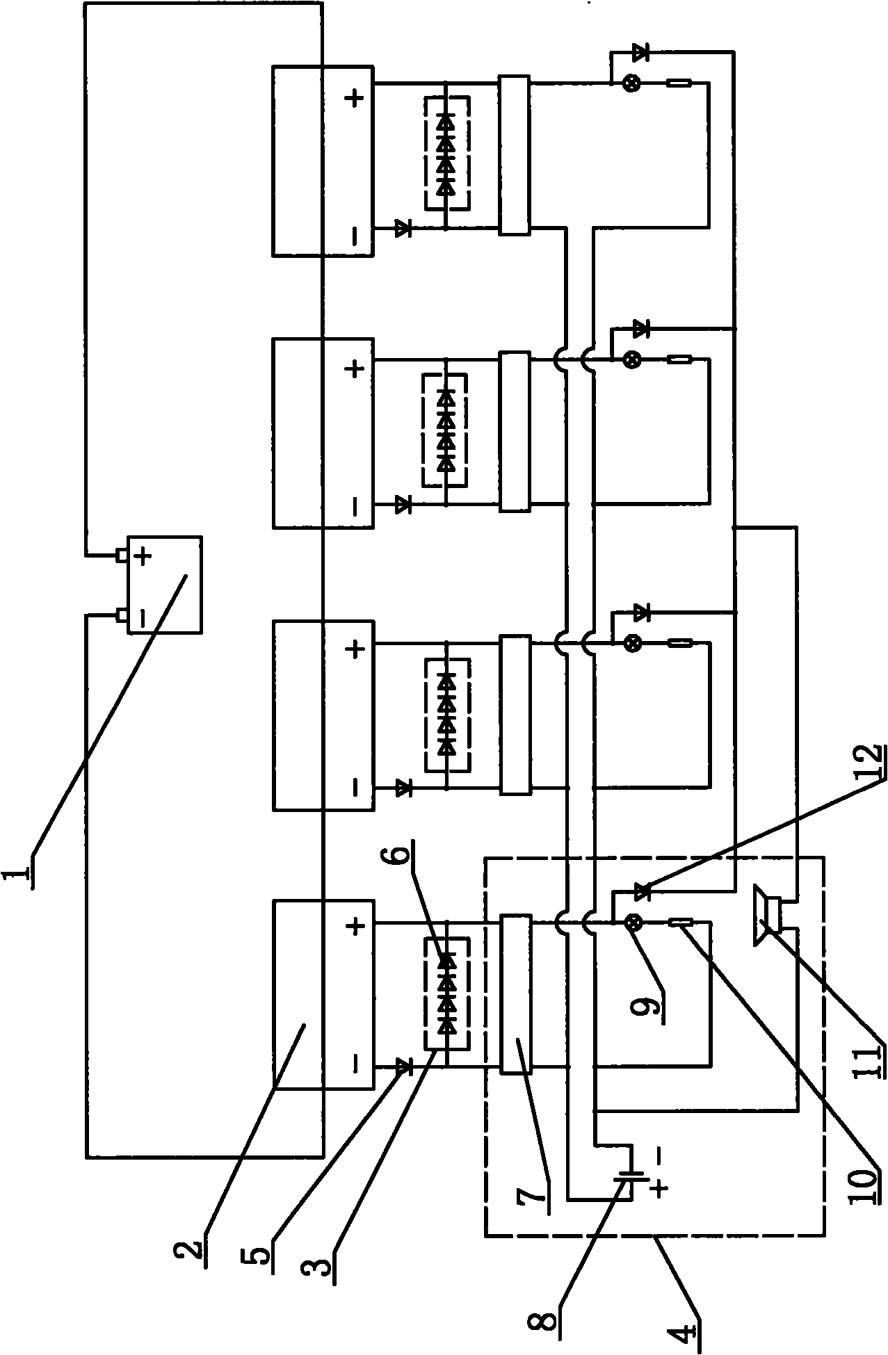
[0035] like figure 2 As shown, the difference between this embodiment and Embodiment 1 is that: the photovoltaic array assembly with fault detection device includes four sets of bypass diode groups 3, four fault detection devices 4, one storage battery 1 and four photovoltaic Assemblies 2, the four photovoltaic modules 2 are connected in series and are connected in series with the battery 1; the bypass diode group 3 is connected in series with a diode 5, and the bypass diode group 3 is connected in series with a diode 5 The formed circuit is connected in parallel with the photovoltaic module 2 respectively, and the fault detection device 4 is respectively connected in parallel with the bypass diode group 3, and each group of bypass diode group 3 includes four diodes 6.

[0036] Each of the fault detection devices 4 described includes a voltage type relay 7, an external power supply 8, a light alarm 9, a protection resistor 10 and an acoustic alarm 11, and the four fault dete...


PUM


Abstract

The invention discloses a photovoltaic array component with a fault detecting device. The photovoltaic array component comprises a bypass diode set, a fault detecting device, a storage battery and at least one photovoltaic component, wherein the photovoltaic component is connected with the storage battery in series; the bypass diode set is connected with one diode in series, and the circuit formed by the bypass diode set being connected with one diode in series is connected with the photovoltaic component in parallel; and the fault detecting device is connected with the bypass diode set in parallel. The photovoltaic array component can quickly judge whether the photovoltaic component is in a fault state by detecting whether the current flows in the bypass diode set connected with the photovoltaic component in parallel, and makes people conveniently and quickly know the fault by the fault detecting device connected with the photovoltaic component.

Description

technical field [0001] The invention relates to a photovoltaic array assembly, in particular to a photovoltaic array assembly with a fault detection device. Background technique [0002] Solar cells made according to the principle of photoelectric conversion have limited output voltage and current. In actual use, many solar cells must be connected in series to form a photovoltaic module, and then the photovoltaic modules must be connected in series and parallel to form a photovoltaic array. [0003] In the work, there is no guarantee that every photovoltaic module that constitutes the photovoltaic array will not fail. The physical manifestation of the failure of the photovoltaic module is that the working current in the module is significantly reduced. The current is "invisible", so the location detection of photovoltaic array faulty components has been plagued by the normal operation of photovoltaic power plants. [0004] At present, a thermal imager is generally used to ...

Claims


Application Information

Patent Timeline
Patent Type & Authority Applications(China)
IPC IPC(8): H01L31/042H01L31/05H02S50/10
CPCY02E10/50
Inventor 王磊
Owner 青岛日月科技发展有限公司
Why Eureka
Try Eureka