
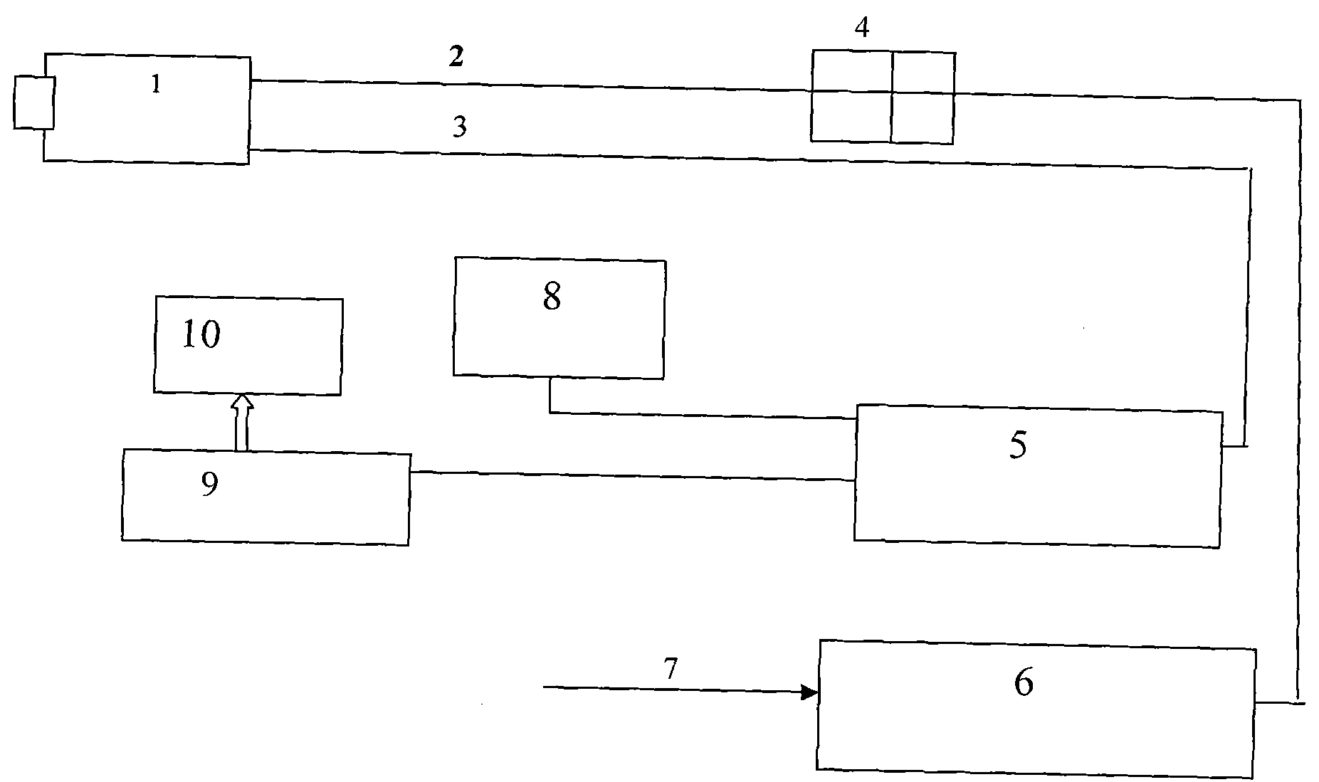
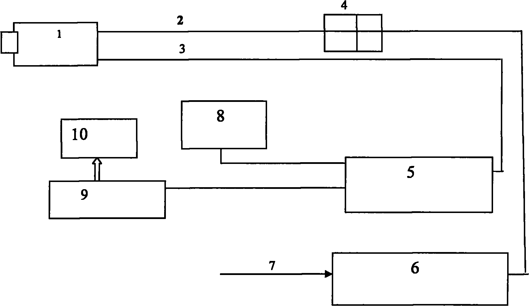
Sintering machine infrared imaging temperature measuring system

A technology of infrared imaging and sintering machine, which is applied in the direction of closed-circuit television system, TV system components, measuring devices, etc., to achieve the effect of simple hard disk video recording function and clear image

Inactive Publication Date: 2010-11-24
NORTHERN ENG & TECH CORP MCC
View PDF5 Cites 5 Cited by
  • Summary
  • Abstract
  • Description
  • Claims
  • Application Information

AI Technical Summary

Problems solved by technology

However, with the continuous improvement of the technological level and the improvement of the user's requirements for the degree of automation, the original basic display function can no longer meet the current needs.

Method used


Image

  • Sintering machine infrared imaging temperature measuring system
  • Sintering machine infrared imaging temperature measuring system

Examples


Embodiment

[0060] Working condition of the present invention:

[0061] Cooling water for water-cooled air seal boots:

[0062] Contact inlet pressure: 0.1~0.4Mpa

[0063] Flow rate: 0.3~1.5m 3 / h

[0064] PH value = 6-8.

[0065] Water-cooled air-sealed protective sleeve air-sealed nitrogen:

[0066] Contact inlet pressure: 0.3~0.6Mpa

[0067] Flow rate: 1.0~3.0m 3 / h.

[0068] System power supply: AC220V 200W.

[0069] The advantages of the present invention are:

[0070] 1) The infrared imaging temperature measurement system adopts the latest ultra-low illumination infrared camera and wide-angle high-temperature resistant lens to ensure long-term and stable work under the normal production of the sintering machine.

[0071] 2) Through the developed sintering machine temperature analysis system software, which integrates image acquisition, video analysis and temperature analysis, it can observe the temperature changes of the sintering machine head and tail in a timely and intui...


PUM


Abstract

The invention belongs to the steel works sintering machine nose tail temperature measuring technical field, in particular relates to a sintering machine infrared imaging temperature measuring system. The system comprises two high temperature detecting instruments which are respectively arranged at the nose and tail, a field control box and a voltage-stabilized source which are connected with the high temperature detecting instrument by virtue of a power wire as well as a video distribution amplifier, a monitor, an industrial controlling machine and a display which are connected with the high temperature detecting instrument by virtue of a video wire; wherein the high temperature instrument is internally provided with a special infrared camera and an infrared pick-up lens, and the industrial controlling machine is internally provided with sintering image temperature analysis system software. The special infrared camera adopts infrared camera with ultra-low illumination, an the infrared pick-up lens adopts a wide angle high temperature resistant lens. The video distribution amplifier is connected with the industrial controlling machine by an RS-485 communication card. The invention has the advantages that: temperature change at the nose and tail can be timely and visually observed, one time slot or the temperature in the time slot can be record, and direct basis can be provided for user production and for solving related problem.

Description

technical field [0001] The invention belongs to the technical field of temperature measurement at the head and tail of a sintering machine in a steel plant, and in particular relates to an infrared imaging temperature measurement system for a sintering machine. Background technique [0002] In the traditional industrial TV design, pinhole water-cooled high-temperature industrial TV systems are usually installed at the head and tail of the sintering machine. The monitoring of the head and tail of the sintering machine in existing sintering projects The point is to display the video screen in real time in the control room and save the video screen to the hard disk recorder through the industrial computer, and there are no other functions. This kind of industrial TV system can only watch video images of sinter cakes. In previous projects, this kind of industrial TV system can basically meet the most common requirements of users. However, with the continuous improvement of the...

Claims


Application Information

Patent Timeline
IPC IPC(8): H04N7/18H04N5/33G01J5/00
Inventor 张乐
Owner NORTHERN ENG & TECH CORP MCC
Learn More