Novel optical track network node structure and FPGA implementation method thereof

A technology of optical rail network and node structure, applied in the field of optical communication network, can solve the problem of lack of reasonable and effective node structure and FPGA implementation method of optical rail technology.

Inactive Publication Date: 2010-11-24
ZHEJIANG UNIV OF TECH
View PDF3 Cites 13 Cited by
  • Summary
  • Abstract
  • Description
  • Claims
  • Application Information

AI Technical Summary

Problems solved by technology

[0004] In order to solve the problem that the existing optical track technology lacks a reasonable and effective node structure and FPGA implementation metho

Method used


Image

  • Novel optical track network node structure and FPGA implementation method thereof
  • Novel optical track network node structure and FPGA implementation method thereof
  • Novel optical track network node structure and FPGA implementation method thereof

Examples


Embodiment 1

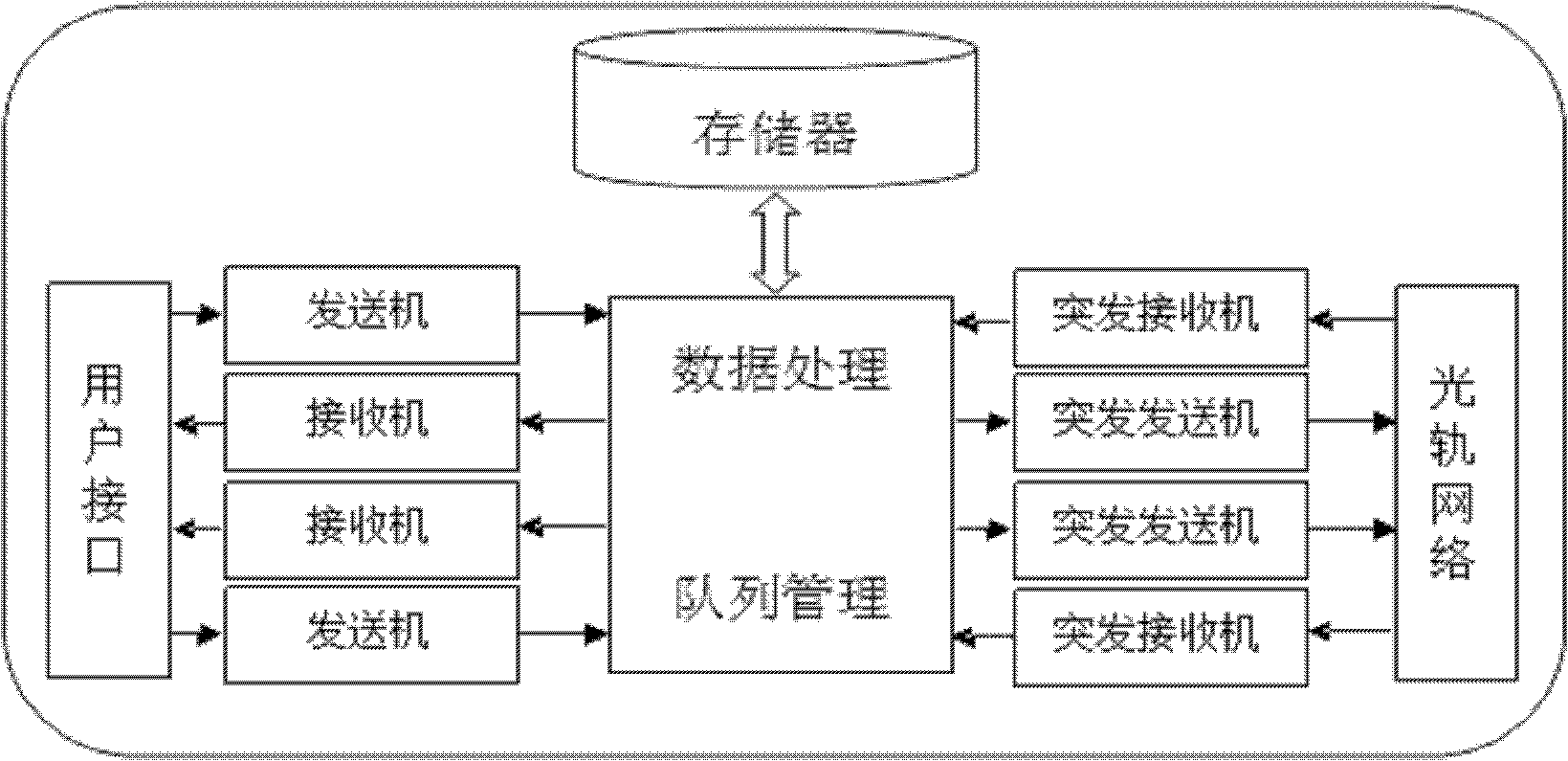
[0054] refer to figure 1 , figure 2 , a new type of optical track network node structure, including a filter / amplification unit, a switching unit, a transceiver unit, an add / drop conversion unit, a multiplexing / demultiplexing unit, and a control unit, and the filtering / amplifying unit is connected to the switching unit respectively , the control unit is connected, and the switching unit is sequentially connected with a multiplexing / demultiplexing unit, an add / drop conversion unit, and a transceiver unit;

[0055] The filter / amplification unit includes a control signal filter, the control signal filter includes a drop filter and an add filter, the drop filter and the add filter are both connected to an optical signal amplifier, and the drop filter The filter filters out the control signal from the wavelength division multiplexing signal of the entrance optical fiber, and connects it to the control unit through the optical fiber; the added filter is responsible for sending the...

Embodiment 2

[0066] Refer to attached Figure 8-9 The specific control implementation process of the FPGA-based optical track node in the optical track communication system and optical connection establishment in the present invention is given.

[0067] Figure 8What is shown is an arbitrary optical network topology, and four nodes N1, N2, N3, and N4 are selected to establish an optical track system. The structure of each node is the same as the above-mentioned design node structure. The light track creation process follows the following steps:

[0068] 1. N1 node FPGA controls and controls the transmitter to send optical track establishment control packet (SP, setup packet) to N2 node, and applies for wavelength λ 1 Build the optical track system, while the FPGA controls the wave trap to block λ 1 through this node.

[0069] 2. The N2 node receives the control packet sent by the N1 node through the drop filter, and then inquires whether the wavelength of the optical track requested by...

Embodiment 3

[0074] This embodiment illustrates the realization of the control of the optical track memory by the FPGA.

[0075] Refer to attached Figure 10-11 , FPGA's Ethernet interface is connected to the Ethernet with a transmission rate of 100Mbps, and the data (electrical signal) from the Ethernet is stored in the built-in DDR SDRAM of Virtex-5. The built-in storage medium total size of the Virtex-5 that the present invention adopts is 256MB, and it is divided into 3 parts, wherein a part size is 16M, is used as the database building space in the optical track, and all the other 2 part sizes are each 120M, used as respectively The receiver buffer and the transmitter buffer are then connected to the transceiver module of the optical track through the high-speed data interface Rocket I / O Transceiver of the FPGA, as the business source of the optical track, instead of directly connecting the Ethernet to the transceiver module of the optical track . The purpose of doing this is twofol...


PUM


Abstract

The invention provides a novel optical track network node structure. The structure comprises a filtering/amplifying unit, a switch unit, a receiving-transmitting unit, an add/drop converting unit, a multiplexing/de-multiplexing unit and a control unit, wherein the filtering/amplifying unit is connected with the switch unit and the control unit respectively; and the switch unit is connected with the multiplexing/de-multiplexing unit, the add/drop converting unit and the receiving-transmitting unit in turn. The novel optical track network node structure has the advantages that: 1, an optical track network test platform is built by using existing mature devices, so that the technology is simple and the cost is relatively low; 2, the test platform can be smoothly upgraded; 3, built-in resources of FPGA can be fully utilized, so that not only the utilization ration of resources is improved, but also the test cost is lowered; and 4, the defects of the optical track technology in experimental research can be overcome, and the learning study effect in experimental teaching can also be improved.

Description

technical field [0001] The invention belongs to the technical field of optical communication networks, and relates to a node structure design and realization method of a novel optical communication network (called light trails, light trails). Background technique [0002] In recent years, with the explosive growth of data communication traffic, the types of business supported by the underlying optical communication network have also undergone great changes, from mainly supporting connection-oriented voice information to supporting data information and burst Data information is the main. In recent years, the considerable progress of optical fiber transmission technology, switching technology, and optoelectronic device technology has made the transmission capacity of a single optical fiber communication channel larger and higher, and the rate is getting higher and higher. From the original single channel 2.5Gb / s to the current single The channel is 20Gb / s, and it is expected ...

Claims


Application Information

Patent Timeline
IPC IPC(8): H04Q11/00
Inventor 乐孜纯侯继斌付明磊
Owner ZHEJIANG UNIV OF TECH
Why Eureka
Try Eureka