
Flat pressing machine, laminating apparatus and laminating method using flat pressing machine and laminating apparatus

A stamping device and plane technology, which is applied in the field of plane stamping devices and lamination devices, can solve problems such as product quality degradation and defective products, and achieve the effect of reducing manufacturing costs

Active Publication Date: 2010-11-24
NIKKO MATERIALS CO LTD
View PDF5 Cites 10 Cited by
  • Summary
  • Abstract
  • Description
  • Claims
  • Application Information

AI Technical Summary

Problems solved by technology

In addition, when the support film of the film-like resin layer 89b is peeled off by an automatic peeling machine in a subsequent process, the above-mentioned scattered resin having a thickness of several tens of micrometers is thermally cured and fixed in a state attached to the smoothed laminate 89. On the smooth laminated body 89, the quality of the product may be reduced, and the product is defective.
On the other hand, the surface of a laminate (not shown) obtained by applying a liquid resist on a substrate 89a having unevenness and drying the liquid resist may be flattened using a planar punching device 85. , when the laminate obtained by applying the liquid resist and drying the liquid resist is conveyed to the planar punching device 85 using the transport film 90 with a roughened surface, and the laminate is heated and pressurized , it is possible that the rough surface of the roughened film is in direct contact with the surface of the above-mentioned laminate and the unevenness of the roughened film is copied to the surface of the above-mentioned laminate

Method used


Image

  • Flat pressing machine, laminating apparatus and laminating method using flat pressing machine and laminating apparatus
  • Flat pressing machine, laminating apparatus and laminating method using flat pressing machine and laminating apparatus
  • Flat pressing machine, laminating apparatus and laminating method using flat pressing machine and laminating apparatus

Examples


Embodiment 1~8 and comparative example 1~8

[0118] Laminates were prepared under the conditions shown in Tables 1 and 2 below. That is, in Examples 1 to 8 and Comparative Examples 1 to 8, the pattern on the substrate 8a is on both surfaces of the substrate 8a, the parallel lines of L (line) / S (space)=50 / 50 μm and Parallel lines of L (line) / S (space)=50 / 50000 μm (=5 cm) are orthogonal. In addition, the height of the prepared pattern (the depth of the unevenness of the uneven surface of the substrate 8a) was three types of 35 μm, 50 μm, and 70 μm, respectively.

Embodiment 9~16 and comparative example 9~16

[0120] Laminates were prepared under the conditions shown in Tables 3 and 4 below. That is, in Examples 9-16 and Comparative Examples 9-16, the pattern on the base material 8a was prepared as four structures of following (1)-(4), respectively. In addition, the height of each pattern was set to 35 μm.

[0121] (1) On both surfaces of the substrate 8a, the parallel line of L / S=50 / 50 μm is perpendicular to the parallel line of L / S=50 / 50000 μm.

[0122] (2) On both surfaces of the substrate 8a, the parallel line of L / S=50 / 500 μm is perpendicular to the parallel line of L / S=50 / 50000 μm.

[0123] (3) On both surfaces of the substrate 8a, the parallel line of L / S=50 / 3000 μm is perpendicular to the parallel line of L / S=50 / 50000 μm.

[0124] (4) On both surfaces of the substrate 8a, the parallel line of L / S=50 / 30000 μm is perpendicular to the parallel line of L / S=50 / 50000 μm.

[0125] In addition, in Examples 1 to 4 and 9 to 12 and Comparative Examples 1, 3, 5, 7 and 9, 11, 13, and ...

Embodiment 17~20 and comparative example 17~20

[0147] A laminate was produced under the conditions shown in Table 5 below. That is, in Examples 17-20, the laminated body 9 was produced under the same conditions as Examples 1-4. In Comparative Examples 17 to 20, laminated body 9 was produced under the same conditions except that the pressure reduction performed in the flat press part in Examples 5 to 8 was not performed.

[0148] Then, with respect to the laminated body 9 of said Examples 17-20 and Comparative Examples 17-20, the defect of the peripheral edge part of a resin layer and the adhesion of a resin layer to a tape-shaped film were evaluated by the following procedure.

[0149] Defects in the peripheral part of the resin layer

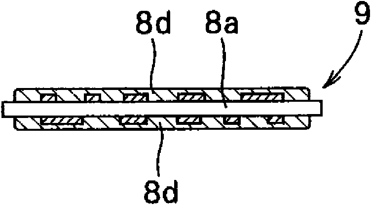
[0150] The peripheral part of the smoothed resin layer 8d laminated on the base material 8a was visually observed, and whether the peripheral part of the resin layer 8d was chipped was evaluated as follows.

[0151] ◯...There is a resin chip around the resin layer 8d.

[0152] ×... The...


PUM

PropertyMeasurementUnit
Thicknessaaaaaaaaaa

Abstract

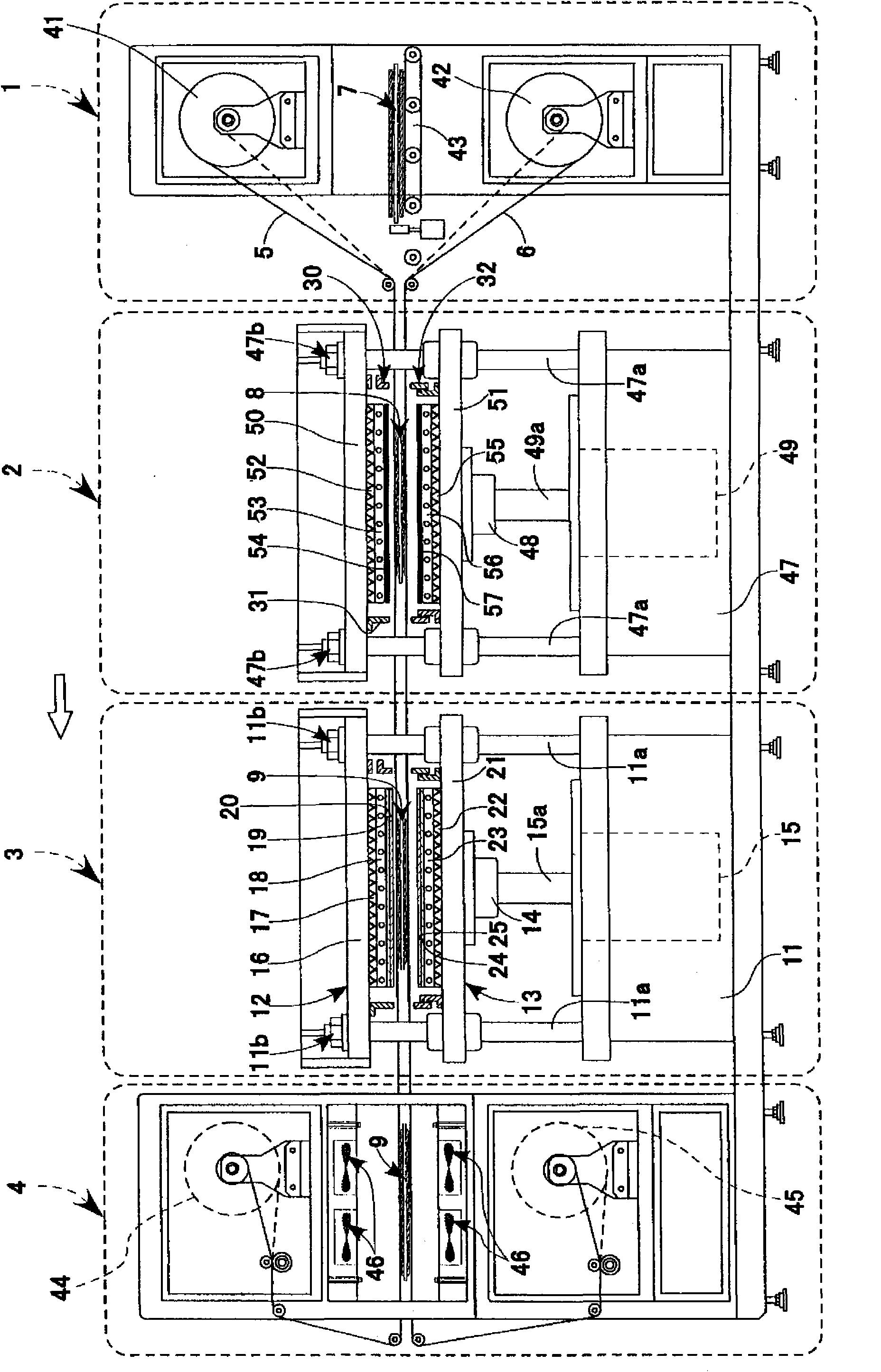
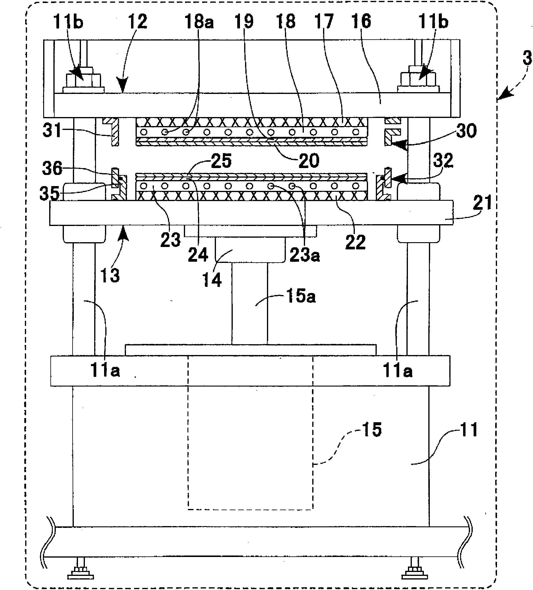
Provided is a flat pressing machine, by which a laminated body can be smoothened, irrespective of unevenness of a base material, cost of a strip-like film for transfer is reduced, a laminated resin is adhered to the strip-like film and does not scatter at the time of peeling the laminated body, and furthermore, a rough surface of the strip-like film is not transferred to the laminated body. A laminating apparatus, and a laminating method using the flat pressing machine and the laminating apparatus are also provided. A flat pressing machine (3) presses a laminated body (8), in which a resin layer (8c) is formed on an uneven surface of a base material (8a), by using facing pressing means, and smoothens a surface of the laminated body (8). The flat pressing means is provided with a pair of strip-like films; a transfer means for transferring the both strip-like films in the longitudinal direction of the film, in a state where the laminated body (8) is sandwiched between the both strip-like films; a hermetically sealed space section (34) for pressing the laminated body (8) by the both pressing means in a depressurized state; and a pressure control means for controlling inside the hermetically-sealed space section (34) in the depressurized state.

Description

technical field [0001] The present invention relates to a flat punching device and a laminating device used in the manufacture of printed circuit substrates, etc., and a lamination method using these devices, and more specifically, to a substrate having unevenness on a printed circuit substrate, etc. A flat punching device and a lamination device that can be used in a build-up method for smoothing the resin layer on the surface, and a lamination method using these devices. Background technique [0002] In recent years, with the miniaturization and high performance of electronic equipment, the density and multilayering of various printed circuit substrates have been developed. The product of the laminated process method. In the multilayering of such a printed circuit substrate, a thermosetting resin composition or a photosensitive resin composition is used as an electrical insulating layer, and the above-mentioned thermosetting resin composition is coated or sprayed on a pre...

Claims


Application Information

Patent Timeline
IPC IPC(8): B29C43/32B29C43/02B29C43/56B29L9/00
CPCB29C2043/561B29C2043/3655B29C43/021B29C2043/5076B29C2043/5808B29C43/184B29C2043/3652H05K3/4611B29C2043/3416B29C43/18B29C43/56
Inventor 安本良一岩田和敏
Owner NIKKO MATERIALS CO LTD
Learn More