Method of cutting laminated body

A technology of laminated bodies and cutting knives, which is applied in metal processing and other directions, can solve problems such as cost and man-hours, wrinkles, and large changes, and achieve the effect of good cut surface quality

Inactive Publication Date: 2010-12-01
FUJIFILM CORP
View PDF8 Cites 4 Cited by
  • Summary
  • Abstract
  • Description
  • Claims
  • Application Information

AI Technical Summary

Problems solved by technology

[0005] In the cutting method described in Japanese Patent Application Laid-Open No. 2006-142445, a cutting device having a base and a fixing mechanism for closely fixing the above-mentioned laminated body to the base is used. The surface shape of the compressive stress of the laminated body has a surface shape in which tensile stress is generated on the surface side of the laminated body and compressive stress is generated on the inner side; however, there is a problem that cost and man-hours are required for base preparation
Furthermore, since pressure acts on the surface of the laminate in the plane direction, problems such as wrinkles and deformation may occur.
[0006] In the cutting method described in Japanese Patent Laid-Open No. 2003-302524, the water content of the optical parts is adjusted to 2 to 4 mass%, but since the water content must be 2 to 4 mass% during cutting, there is an optical zero. Problems of cost and man-hours spent on parts storage management and process management
[0007] In addition, in Japanese Patent Application Laid-Open No. 2006-142445 and Japanese Patent Laid-Open No. 2003-302524, the probability of delamination (delamination between layers) or cracks when the laminate is cut varies depending on the elongation of the materials constituting the laminate. There is a large variation in this situation without any testing

Method used


Image

  • Method of cutting laminated body
  • Method of cutting laminated body
  • Method of cutting laminated body

Examples


Embodiment

[0080] The following examples of the present invention are given to illustrate the present invention in detail. In addition, the materials, usage amounts, proportions, processing contents, processing procedures, etc. described in the following examples can be appropriately changed as long as they do not deviate from the spirit of the present invention. Therefore, the scope of the present invention should not be limited to the interpretation of the following specific examples.

no. 1 Embodiment

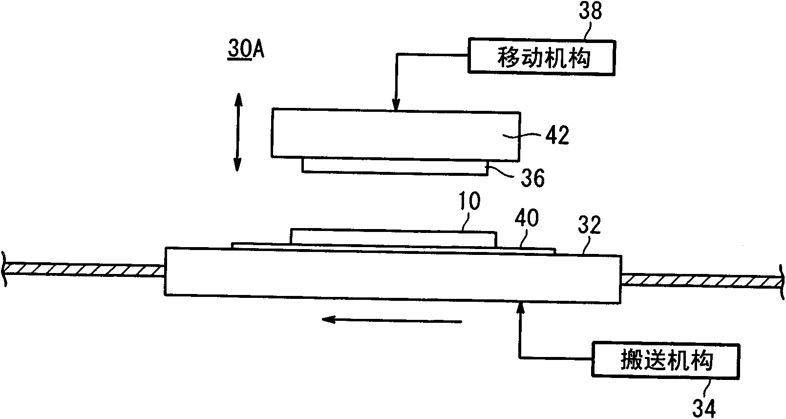
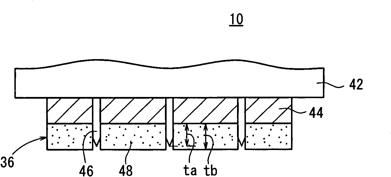
[0082] According to the first cutting method (refer to Figure 7 ), so that the upper surface of the multilayer film 16 (the upper surface of the second protective film 18b) is opposite to the blade of the cutting knife 46 and the laminated film 10 is carried and fixed on the conveying table 32, from the multilayer film 16 side toward the partition The film 12 is cut.

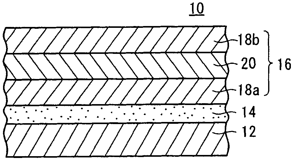
[0083] (laminated film 10)

[0084] The structures of various films constituting the laminated film 10 are as follows.

[0085] Separation film 12: PET film with a thickness of 40 μm.

[0086] Adhesive 14: 30 μm in thickness.

[0087] 1st protective film 18a: TAC film (trade name manufactured by Fuji Film Co., Ltd.: FUJITAC) with a thickness of 40 μm.

[0088] Polarizer 20: PVA film with a thickness of 28 μm.

[0089] Second protective film 18 a : TAC film (trade name: FUJITAC manufactured by Fuji Film Co., Ltd.) with a thickness of 40 μm.

[0090] The elongation of the first protective film 18a and the s...

Embodiment 1~17、 comparative example 1~20

[0092] Details of Examples 1 to 17 and Comparative Examples 1 to 20 are shown in Table 2 and Table 3 below. In addition, the data other than Examples 1-17 and Comparative Examples 1-20 in Table 2 and Table 3 are shown as a reference example. The cutting speed v is the actual measured value, and the sponge hardness is the value measured with an Oscar C hardness tester (ASKER C).


PUM


Abstract

The present invention provides a method of cutting a laminated body, capable of obtaining good cutting surface quality without cost and labour hour even that a part (film) of the laminated body (10) has a low elongation rate, wherein the laminated body (10) is cut by a cutting knife (46). The laminated body (10) has a separation film (12) and a multilayer film (16) stacked on the separation film (12) through adhesive agent (14). The multilayer film (16) has a first protection film (18a) stacked on the adhesive agent (14), a polarization mirror (20) stacked on the first protection film (18a), and a second protection film (18b) stacked on the polarization mirror (20). Furthermore, a speed (cutting speed v) of the cutting knife (46) to the laminated body (10) is adjusted to more than 8mm/sec, preferably more than 10mm/sec to cut the laminated body (10).

Description

technical field [0001] The present invention relates to a method for cutting a laminate in which one or more films are laminated with adhesives using a jig for cutting. Background technique [0002] Recently, methods described in JP-A-2006-142445 and JP-A-2003-302524 are known as a method of cutting a laminate in which one or more films are laminated with an adhesive using a cutting blade. [0003] The cutting method described in Japanese Patent Application Laid-Open No. 2006-142445 is a method of reducing the compressive stress applied to the laminated body when the cutting blade cuts the laminated body. The reduction of the compressive stress is applied to the surface side of the laminated body It is carried out under the condition that tensile stress is applied and compressive stress is applied to the inner side. Thus, in the cutting process, the internal stress from the cut surface toward the cutting blade can be relieved, and the closeness between the cut surface and t...

Claims


Application Information

Patent Timeline
Patent Type & Authority Applications(China)
IPC IPC(8): B26D1/04B26D7/08
CPCB26D1/085B26D5/005B26D2001/0053
Inventor 中山武彦
Owner FUJIFILM CORP
Why Eureka
Try Eureka