
Electrode wire for slow wire EDM cutting

A technology of electrode wire and slow-moving wire, which is applied in the field of electrode wire, can solve the problems of damage to the wire-feeding part structure and guide device of the slow-moving wire cutting machine, the reduction of the mechanical properties of the electrode wire, and the limitation of the applicability of the electrode wire, etc., to achieve high cutting Surface quality, optimized electrical properties, and the effect of excellent surface quality

Active Publication Date: 2017-12-01
NINGBO BODE HIGHTECH CO LTD
View PDF8 Cites 3 Cited by
  • Summary
  • Abstract
  • Description
  • Claims
  • Application Information

AI Technical Summary

Problems solved by technology

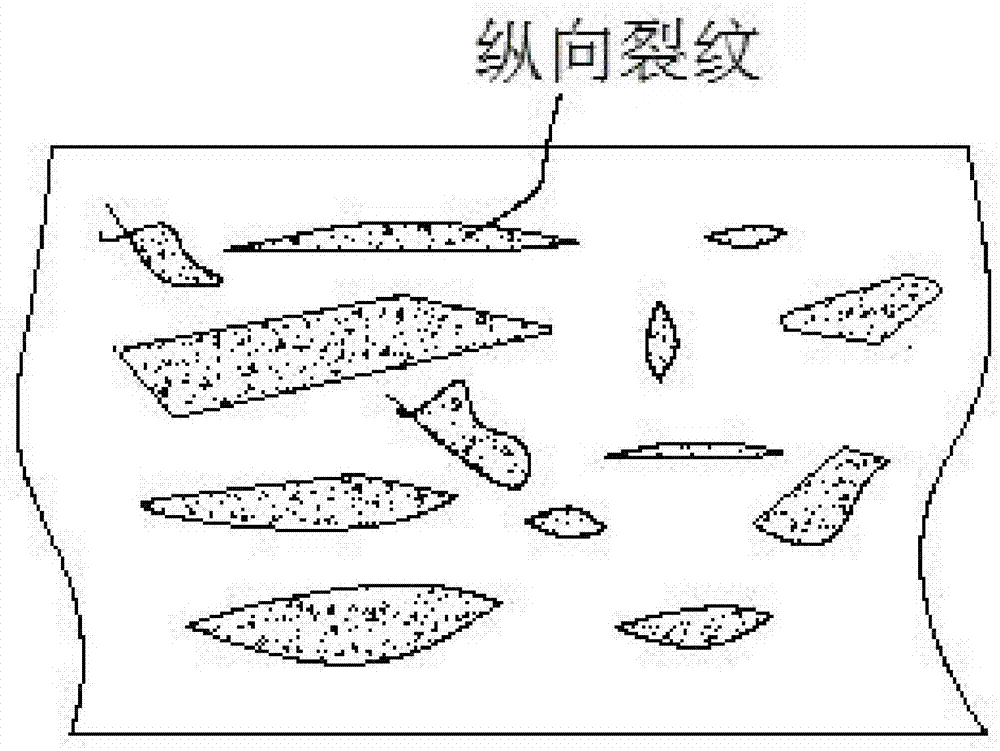
[0012] 3. Electrode wire with transverse irregular cracks on the surface. The surface of this electrode wire contains β phase and γ phase, or a mixture of the two phases. Because of cracks and γ phase brass alloys containing high zinc, this electrode wire The cutting speed of the wire is faster than the wire electrode in 1 and 2, but this wire electrode has an unavoidable disadvantage: due to the existence of transverse cracks in the surface layer, the moving direction of the wire electrode is along the vertical direction of the crack during use, so this The existence of such cracks will damage the wire feeding part structure and guiding device of the slow wire cutting machine; at the same time, because the cracks are perpendicular to the axial direction of the electrode wire, the mechanical properties of the electrode wire will also be reduced, and some have requirements for the mechanical properties of the electrode wire In some occasions, the applicability of this electrode wire will also be limited
[0013] The electrode wire materials currently used by users are nothing more than the above-mentioned types. According to the previous discussion, the above-mentioned electrode wires are all electrode wires used under specific working conditions.

Method used


Image

  • Electrode wire for slow wire EDM cutting
  • Electrode wire for slow wire EDM cutting
  • Electrode wire for slow wire EDM cutting

Examples


Embodiment

[0063] 1.1. Purchasing copper, zinc, phosphorus, rare earth, sodium, potassium, magnesium, calcium, aluminum, silicon, manganese, titanium, chromium and iron raw materials at an appropriate price in the market, and start batching after passing the chemical analysis;

[0064] 1.2. Carry out alloying ingredients according to the alloy composition shown in Table 1, and transport the prepared raw materials to the smelting site for smelting;

[0065] 1.3. Melting is an important process for manufacturing cutting wire materials. All alloying elements are added in this process. Melting adopts upward continuous casting, and the casting temperature is selected as 950-1250°C;

[0066] 1.4. Plastic processing and recrystallization annealing: This process mainly refers to the process of peeling, recrystallization annealing, and plastic processing of different passes on the manufactured upward continuous casting slab, and setting the specifications of the busbar according to the requirement...


PUM

PropertyMeasurementUnit
widthaaaaaaaaaa
lengthaaaaaaaaaa
tensile strengthaaaaaaaaaa

Abstract

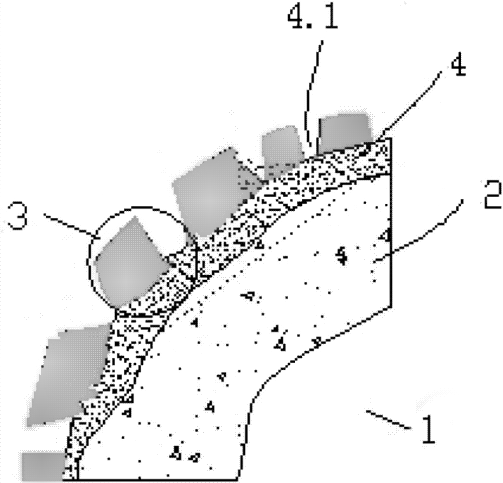
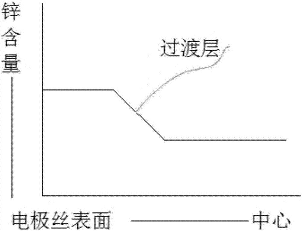
An electrode wire used for spark cutting of low-speed wire cutting comprises an electrode wire body. The electrode wire body is composed of a core material and a surface metal layer, wherein the core material is made of an alloying brass material, and the surface metal layer covers the core material. A transition layer is arranged between the core material and the surface metal layer. The alloying brass material is composed of, by weight, 58.0-65.0% of copper and the balance zinc, a small quantity of adding elements and inevitable impurities. The surface metal layer is composed of copper, zinc, adding elements and inevitable impurities, wherein the zinc content is larger than 52 wt% and smaller than 68 wt%, and the surface metal layer is distributed in a fracture shape longitudinally. Compared with the prior art, the electrode wire has the advantages that the manufactured electrode wire is stable in discharge performance, the cutting speed is increased, a wire feeding part and a guiding device of low-speed wire cutting equipment are prevented from being damaged, a machining technique of the electrode wire is simple, the application range is wide, the cost is low, and broad market prospects are achieved.

Description

technical field [0001] The invention relates to an electrode wire (Electro Discharge Machining) used for slow wire electric discharge machining. Background technique [0002] As we all know, EDM is a special processing method that uses the electric erosion effect generated by the pulse discharge between the two electrodes immersed in the working fluid to etch away the conductive material. It is also called electric discharge machining or electric erosion machining. During production, the electric discharge cutting process is to erode the metal of the processed part by generating electric sparks in the area between the processed part and the electrode wire, and through the movement of the electrode wire along its own axial direction or the processing part along the electrode wire diameter Translate in the direction to electro-corrode and process the workpiece according to the required shape. [0003] Generally speaking, the positive electrode of the power supply generator of...

Claims


Application Information

Patent Timeline
Patent Type & Authority Patents(China)
IPC IPC(8): B23H1/06
CPCB23H1/06
Inventor 孟宪旗万林辉林火根梁志宁陈小军吴桐
Owner NINGBO BODE HIGHTECH CO LTD
Learn More