Fining twisted steel-based lifting appliance and lifting method thereof

A technology of fine-rolled rebar and hoisting method, which is applied in the direction of hoisting devices, etc., which can solve problems such as troublesome operation, short screw length, and small space where hoisting equipment cannot be installed, so as to achieve the effects of convenient interception, reduced consumption, and shortened construction period

Inactive Publication Date: 2010-12-01
TIANJIN 20 CONSTR
View PDF5 Cites 1 Cited by
  • Summary
  • Abstract
  • Description
  • Claims
  • Application Information

AI Technical Summary

Problems solved by technology

However, the screw and connector need to be specially processed, and the length of the screw is short, so the lifting sequence needs to be changed frequently during lifting
In the above two cases, on the one hand, the space is too small to install hoisting equipment, and on the other hand, the screw rods of the force group are frequently replaced during the hoisting of the water tank, which is troublesome to operate

Method used


Image

  • Fining twisted steel-based lifting appliance and lifting method thereof
  • Fining twisted steel-based lifting appliance and lifting method thereof
  • Fining twisted steel-based lifting appliance and lifting method thereof

Examples


Embodiment 1

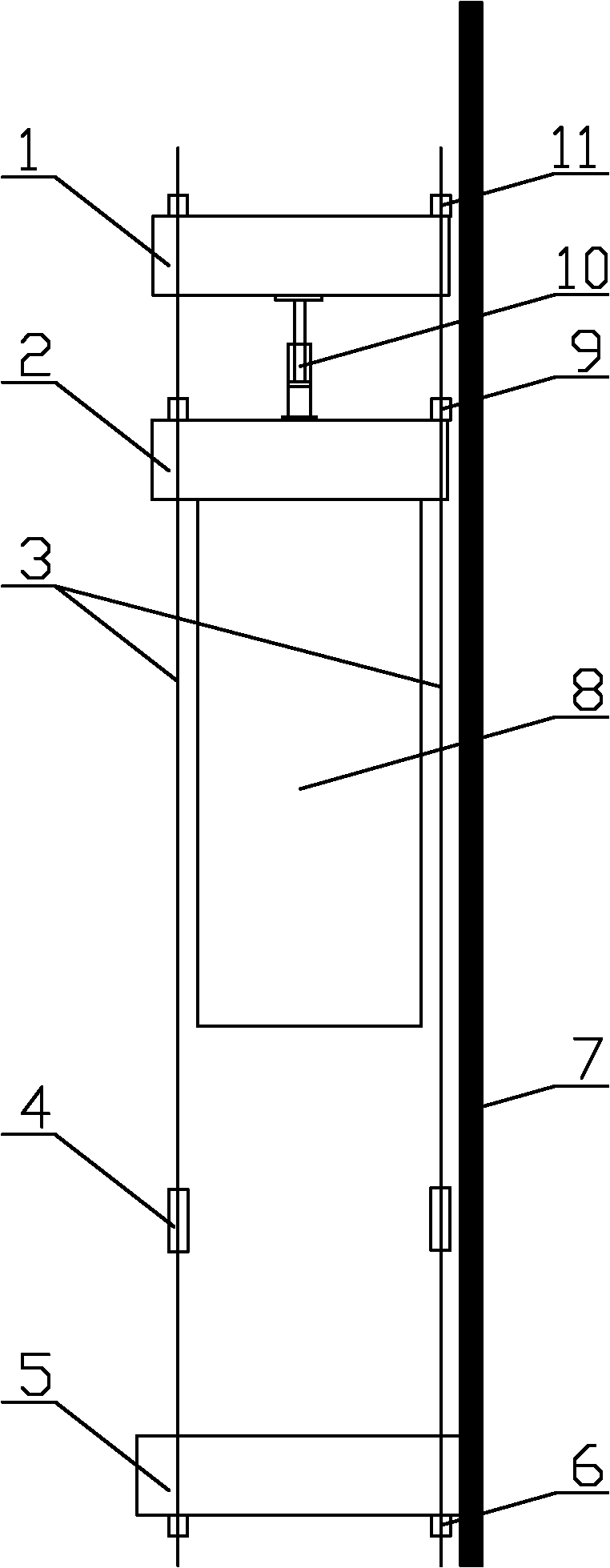
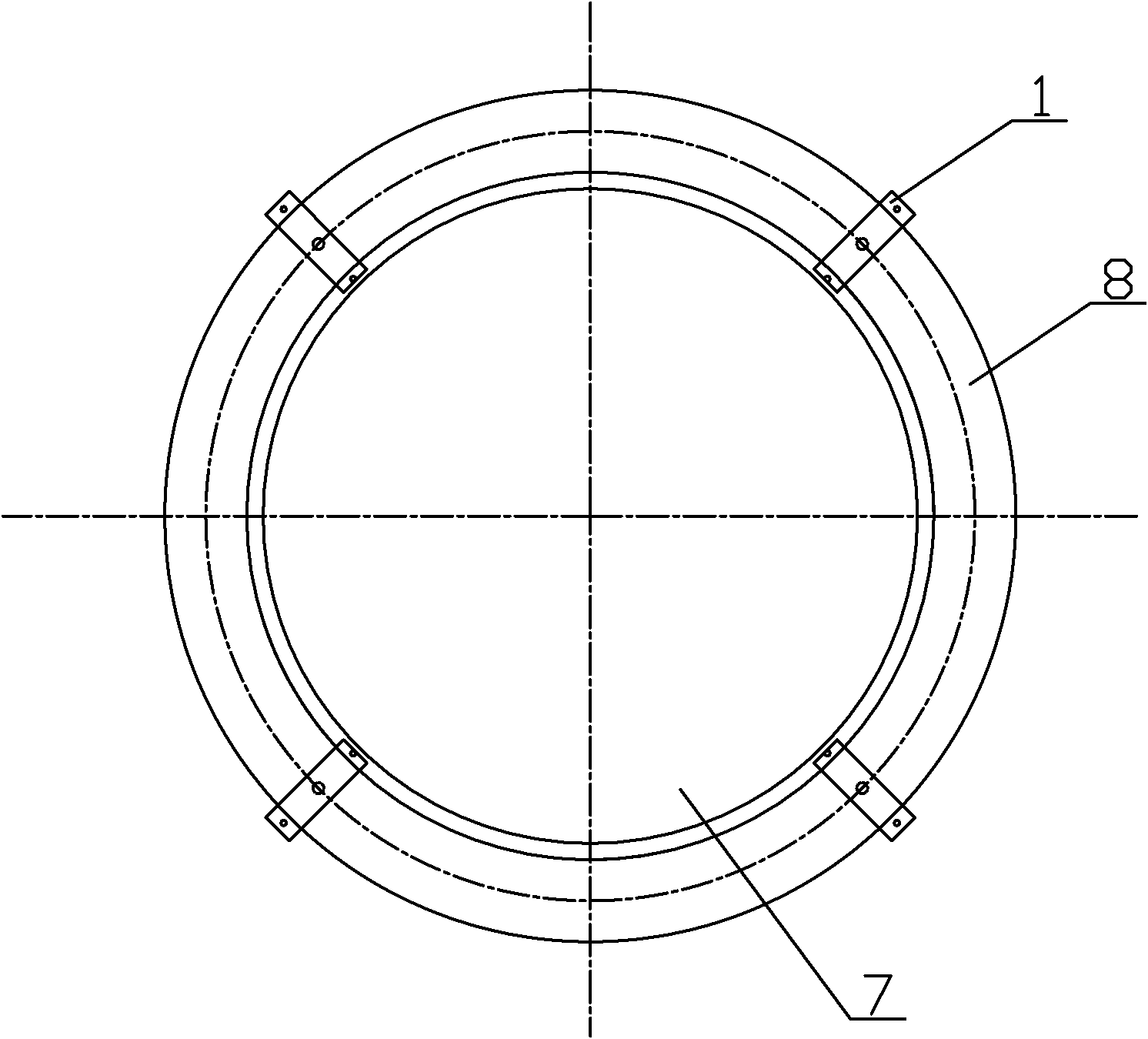
[0027] During the upside-down construction of the 100-ton converter shell 7 of Ronggang 3#, since the gap between the furnace shell 7 and the support ring 8 is very narrow, (6290-5990) / 2=150mm, construction methods such as winches cannot be used. The center-through hydraulic jack 10 cannot be placed, but the finish-rolled rebar 3 can be placed, so the finish-rolled rebar 3 is used as the spreader.

[0028] Such as figure 1 and figure 2 As shown, the specific upgrading process is as follows:

[0029] Four lifting points are set on the periphery of the furnace shell 7, and each lifting point bears a load of 132.4 / 4=34.1 tons. According to the size of the outer diameter of the furnace shell 7, the number of hanging points can be changed.

[0030] In this embodiment, the furnace shell 7 is the object to be hoisted, and the support ring 8 is the fixed reference object. At this time, the furnace shell 7 and the support ring 8 are in an upside-down state. The first fixed crossbe...

Embodiment 2

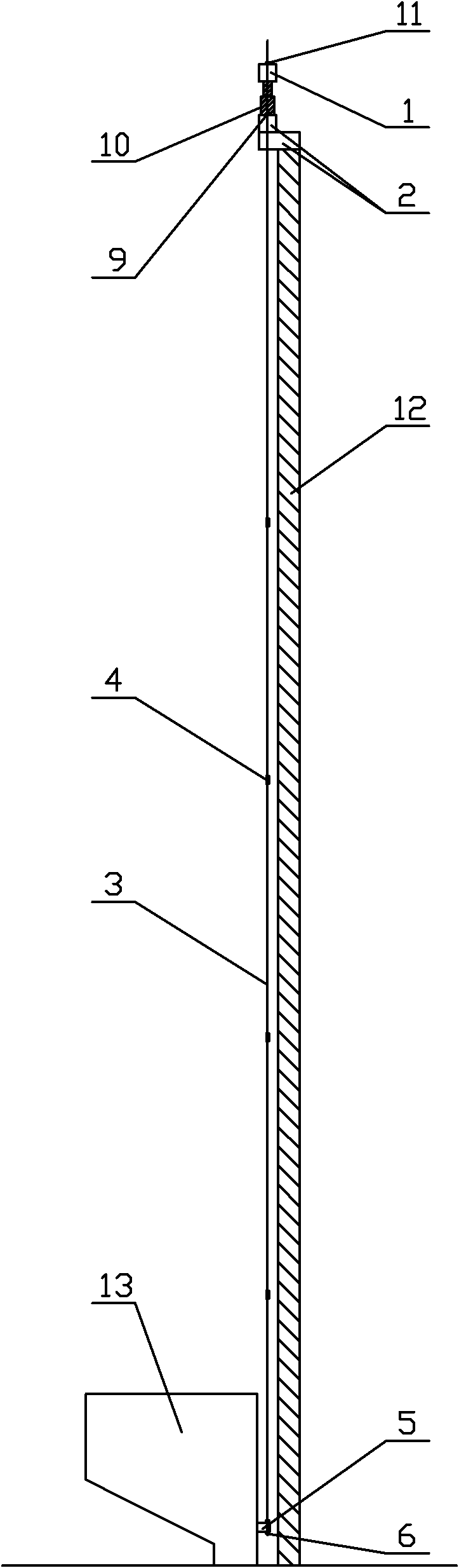
[0036] Such as Figure 3 to Figure 5 As shown, the water tank 13 of the outer water tower of the first-phase steelmaking workshop of Ronggang is on the top of the tower body 12, the height of the tower body 12 is 78 meters, and the water tank 13 is a concrete structure.

[0037] The existing technology is to prefabricate the water tower 13 at the bottom of the tower body 12, and then use carefully processed 3-meter-long round steel to make a threaded screw. The screw is connected by a connector, and then the hydraulic synchronization system is used for lifting. Since the screw rod and connector need to be specially processed, and the length of the screw rod is relatively short, the lifting group needs to be replaced every 3 meters during the lifting process, and the lifting speed is very slow.

[0038] The present invention adopts the 12-meter-long finish-rolled rebar and the anchor as the lifting tool, and the lifting group can be replaced every 12 meters.

[0039] In this e...


PUM


Abstract

The invention discloses a fining twisted steel-based lifting appliance and a lifting method thereof. The lifting appliance comprises a first fixed beam; fining twisted steel passes through the two ends of the first fixed beam through an anchor; the middle of the fining twisted steel passes through a second fixed beam through an anchor; a hydraulic jack is arranged above the second fixed beam; the top of the hydraulic jack is provided with a movable beam; and the fining twisted steel passes through the two ends of the movable beam through an anchor. The lifting method comprises the following steps of: welding the first fixed beam on a lifted object, and welding the second fixed beam on a fixed reference object; fastening the anchor on the movable beam and the anchor on the first fixed beam, and lifting the hydraulic jack; loosening the anchor on the movable beam, fastening the anchor on the second fixed beam, and retracting the hydraulic jack; and reciprocating the movable beam until the lifted object is in position. The fining twisted steel and the anchors are adopted to serve as the lifting appliances for the first time so as to lift equipment in a small space and avoid frequent replacement of stress groups.

Description

technical field [0001] The invention relates to a device and method for lifting loads, in particular to a device and working method for lifting loads in a narrow space. Background technique [0002] At the current level of technology, Scres-thread steel bars for the prestressing of concrete, also known as finish-rolled steel bars, are widely used in continuous beams and large-scale hydraulic engineering, industrial and civil buildings. Frame structure, highway, railway large and medium-span bridges, nuclear power plants and ground anchors and other projects. It has the advantages of simple connection and anchoring, strong adhesion, safe and reliable tension anchoring, and convenient construction. The application of finish-rolled rebar can save steel bars, reduce component area and weight, and its use is usually only as an important part of fixed components and structures. [0003] In the case of very narrow construction space, such as converter inversion, because the gap b...

Claims


Application Information

Patent Timeline
Patent Type & Authority Applications(China)
IPC IPC(8): B66F11/00
Inventor 杜军科韩文哲徐兰柱丁学芳王岩
Owner TIANJIN 20 CONSTR
Why Eureka
Try Eureka