Counter-pulled type rib retaining wall of pre-stressing force cantilever

A pre-stressed, cantilever-type technology, applied in the processing of building materials, construction, artificial islands, etc., can solve the problems of poor seismic force resistance, easy damage, and poor integrity of the retaining wall, so as to reduce the side The effect of reducing the amount of deformation, enhancing the anti-collision performance, and having a wide range of applications

Inactive Publication Date: 2010-12-01
SHANDONG UNIV
View PDF6 Cites 13 Cited by
  • Summary
  • Abstract
  • Description
  • Claims
  • Application Information

AI Technical Summary

Problems solved by technology

The reinforced earth retaining wall is a reinforced body structure, which is suitable for road shoulder retaining walls and embankment retaining walls in general areas, but it should not be built in landslides, water erosion, collapse and other unfa Poor ability of earthquake force
Interanchored thin-walle

Method used


Image

  • Counter-pulled type rib retaining wall of pre-stressing force cantilever
  • Counter-pulled type rib retaining wall of pre-stressing force cantilever
  • Counter-pulled type rib retaining wall of pre-stressing force cantilever

Examples


Embodiment 1

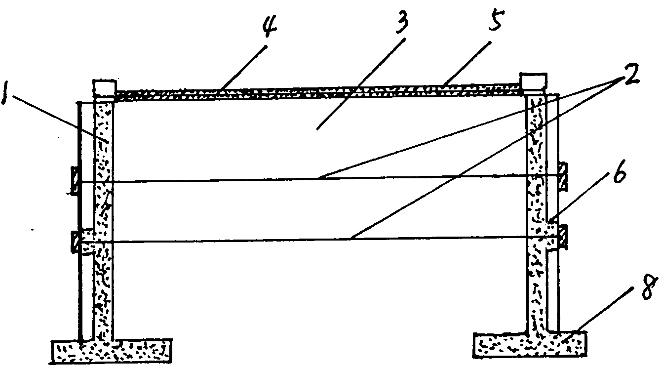
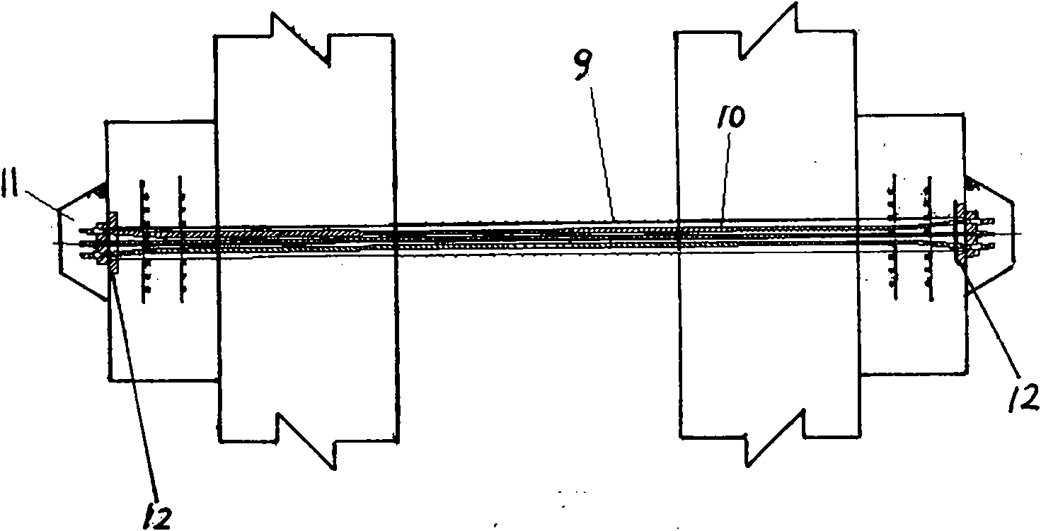
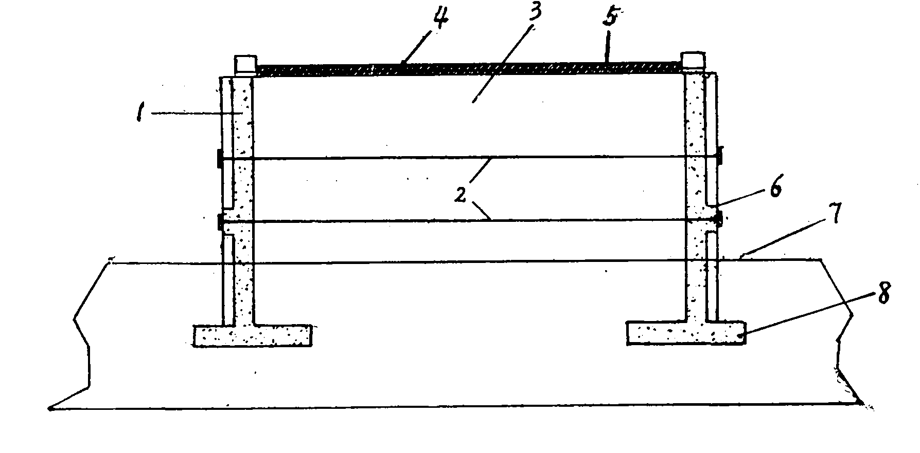
[0015] The retaining wall is composed of a cantilever reinforced concrete retaining wall 1 arranged symmetrically on both sides of the roadbed and a row of paired anchor cables 2 running through the width of the roadbed. The cross section of the retaining wall 1 is a single layer, and the retaining wall Under the body 1, there is a bottom plate 8 buried under the ground line 7, and the middle part is provided with ribs 6 for installing anchor piers 11. There are plastic sleeves 9 outside the anchor cables 2, and the anchor cables are 5 bundles of 7φ5 steel strands. There is a grouting protective layer between the plastic pipe sleeve 9 and the steel strand 10, the two ends of the anchor cable 2 are connected to the anchor plate 12 on the outside of the rib 6, and the embedded road structure is arranged on the top of the cantilever retaining wall 1 5, the embankment fill 3 is filled between the top of the ground line 7 and the cantilever retaining wall 1 and the pavement structur...

Embodiment 2

[0017] The retaining wall is composed of a cantilever reinforced concrete retaining wall 1 arranged symmetrically on both sides of the subgrade and connected with an anchor cable 2 running through the width of the subgrade. The cross section of the retaining wall 1 is stepped and has two layers, each There are two rows of opposing anchor cables 2 across the width of the subgrade. Under the retaining wall 1, there is a bottom plate 8 embedded below the ground line 7. The middle part is provided with ribs 6 for installing anchor piers 11. The outer anchor cables 2 are There are plastic sleeves 9, and the anchor cables are 5 bundles of 7φ5 steel strands 10. There is a grouting protective layer between the plastic sleeves 9 and the steel strands 10, and the two ends of the anchor cables 2 have anchors connected to the outer sides of the ribs 6. Backing plate 12, on the top of the cantilever retaining wall 1 on the upper floor, is provided with reinforcing bars 4 embedded in the pav...

Embodiment 3

[0019] A highway has a section of clay roadbed with a height of 9.0m. A stepped double-layer cantilever retaining wall is adopted.

[0020] The lower cantilever retaining wall 1 is 6m high, 0.5m wide, and the bottom plate 8 is 0.5m thick; the upper cantilever retaining wall 1 is 3.35-4.5m high, 0.4m wide, and the bottom plate 8 is 0.5m thick. The upper cantilever retaining wall 1 is provided with one row of tensioned prestressed anchor cables 2 penetrating the subgrade, with a longitudinal spacing of 3m, and the lower cantilever retaining wall 1 is provided with two rows of tensioned prestressed anchor cables 2 penetrating the subgrade, with a longitudinal spacing of 3m. . The prestressed tension locking values ​​of the anchor cable 2 are 100kN, 800kN, and 800kN from top to bottom.

[0021] The part of the wall above the ground line 7 must be provided with drain holes, with a distance of 2 to 3 meters, arranged staggered up and down, left and right, and φ7.5cm PVC drain pipe...


PUM


Abstract

The invention provides a counter-pulled type rib retaining wall of a pre-stressing force cantilever. The retaining wall is formed by connecting cantilever type reinforced concrete earth-retaining wall bodies, which are symmetrically arranged on two sides of a roadbed, with a counter-pulled anchor rope which runs through the width of the roadbed, wherein the cross sections of the earth-retaining wall bodies have single-layered shapes or ladder-type multi-layer shapes. A base plate is arranged below the earth-retaining wall bodies, and ribs for mounting anchor piers are arranged in the middle parts of the earth-retaining wall bodies; a plastic pipe sleeve is arranged outside the counter-pulled anchor rope; the counter-pulled anchor rope comprises n bundles of steel stranded wires; and a grouting protective layer is arranged between the plastic pipe sleeve and the steel stranded wires. The integrity, the skid resistance, the overturn resistance, the collision resistance and the earthquake resistance of the earth-retaining wall can meet operating requirements, the limit height of the earth-retaining wall is higher than that of the conventional earth-retaining wall, and the earth-retaining wall has a wide application range and a low requirement on the foundation bearing capacity.

Description

Technical field: [0001] The invention belongs to the field of civil engineering, and relates to a retaining wall structure, in particular to a prestressed cantilever double-tensioned retaining wall suitable for filling soil of various soil quality high roadbeds. Background technique: [0002] There are many ways and types of conventional retaining walls, the most common ones are gravity type, cantilever type, buttress type, anchor rod, anchor plate, reinforced soil, and inter-anchored thin-wall type. The gravity retaining wall relies on the weight of the wall itself to balance the lateral pressure of the soil behind the wall. The material of the wall is mortar block stone or reinforced concrete. It is high and has a single landscape effect, especially in areas where stone resources are scarce, it is not economical to implement. The cantilever retaining wall adopts reinforced concrete structure, which should be used in the embankment section where stone materials are scarce ...

Claims


Application Information

Patent Timeline
IPC IPC(8): E02D29/02E04G21/12
Inventor 宋修广李英勇张宏博薛志超王红红弋晓明江屹东
Owner SHANDONG UNIV
Why Eureka
Try Eureka