Urea mixing device

A technology of mixing device and urea, which is applied in the direction of muffler, exhaust device, mechanical equipment, etc., can solve the problems of ammonia leakage, reduce sediment, etc., achieve the effect of improving NOx conversion efficiency and reducing the uneven distribution of ammonia

Inactive Publication Date: 2010-12-01
TSINGHUA UNIV
View PDF5 Cites 20 Cited by
  • Summary
  • Abstract
  • Description
  • Claims
  • Application Information

AI Technical Summary

Problems solved by technology

Although the urea SCR system is being promoted worldwide, there are still some problems to be solved, such as how to improve N

Method used


Image

  • Urea mixing device
  • Urea mixing device
  • Urea mixing device

Examples


Embodiment

[0020] An experiment was carried out on a 4.5L diesel engine to compare the conversion efficiency of NOx under various working conditions when the urea mixing device was installed and when the urea mixing device was not installed. The test results show that installing a urea mixing device can increase the NOx conversion efficiency by about 5%-10% under the same working conditions. The test conditions are shown in Table 1.

[0021] Table 1 Comparative test of each working condition

[0022]


PUM

PropertyMeasurementUnit
Angleaaaaaaaaaa
Angleaaaaaaaaaa
Thicknessaaaaaaaaaa

Abstract

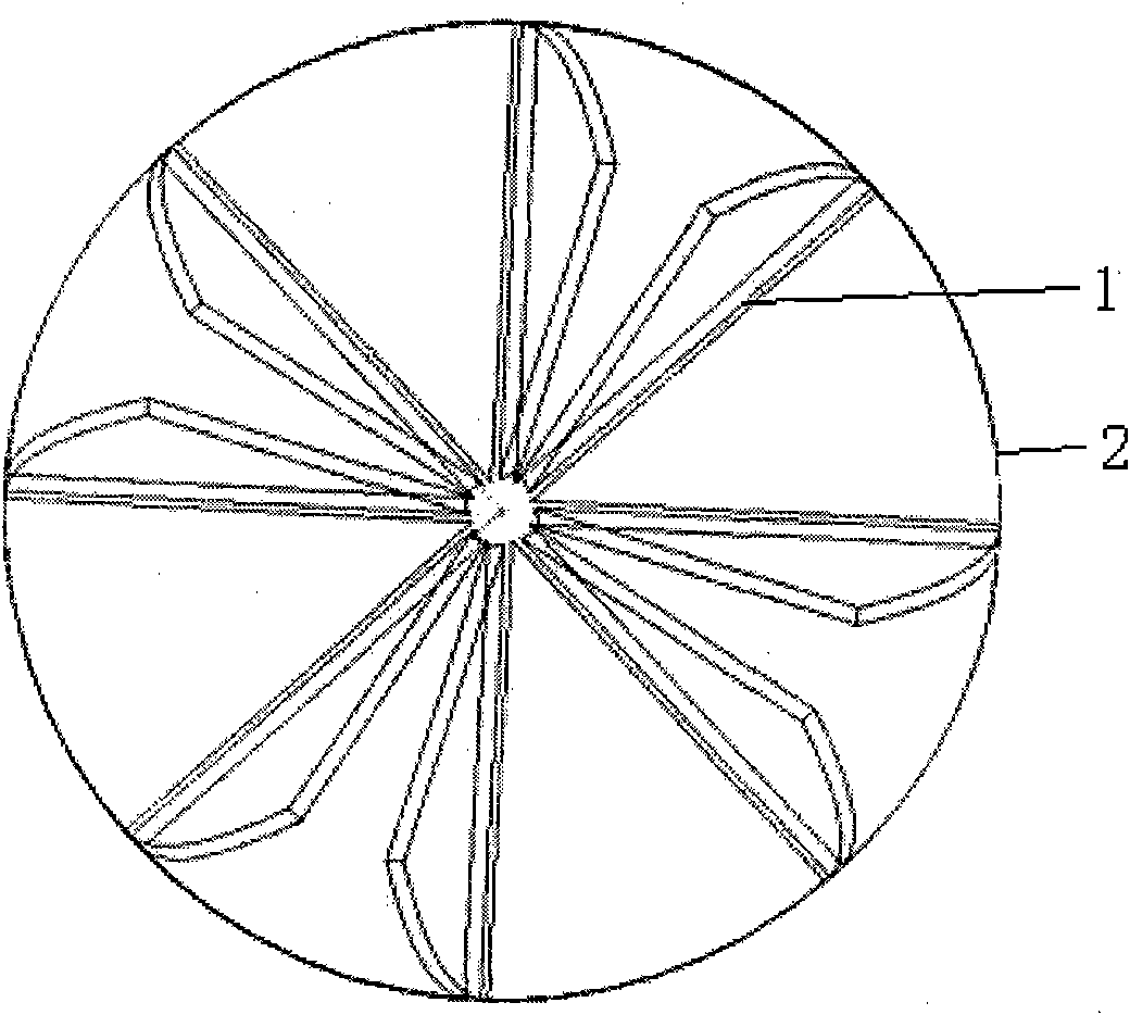
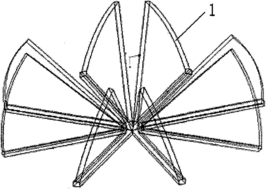
The invention relates to a urea mixing device, which is characterized by comprising at least two groups of blade pairs, wherein each group of blade pairs comprise two blades of which the folding directions are opposite; and the blades are distributed on the same round section uniformly and are crossed at the circle center of the round section. The device is arranged on the rear end of a urea nozzle in an exhaust pipe; exhausted gases generate violent gas flow disturbance under the turbulent effect of the blades when mixed; strong turbulent flowing motion makes the exhausted gases and atomized urea mixed more uniformly and accelerates the evaporation and decomposition of urea solution; and thus, the NOx conversion efficiency is improved, and ammonia leakage caused by nonuniform ammonia distribution is reduced. Tests show that the NOx conversion efficiency of a urea SCR system having the urea mixing device can be improved by as much as 10 percent.

Description

technical field [0001] The invention relates to a urea mixing device, in particular to a urea mixing device used in a NOx (nitrogen oxide) urea SCR (selective catalytic reduction) system of a diesel engine, and belongs to the field of automobile tail gas treatment and internal combustion engine emission control. Background technique [0002] The urea mixer is a device used in the urea SCR system, which is mainly used to improve the NOx conversion efficiency of the urea SCR system and reduce the formation of deposits. The urea SCR system is one of the most effective technologies for reducing NOx emissions from heavy-duty diesel engines. In recent years, people have gradually deepened the research on SCR technology of urea for vehicles, and constantly solved various problems in the application. The urea SCR technology for vehicles has been put into practical use in Europe and is being promoted and used all over the world. In China, due to the high sulfur content of diesel oi...

Claims


Application Information

Patent Timeline
IPC IPC(8): F01N3/20B01D53/94
Inventor 赵彦光帅石金肖建华王建昕
Owner TSINGHUA UNIV
Why Eureka
Try Eureka