
Omnibearing tilt sensor based on machine vision

A technology of tilt sensor and machine vision, applied in the direction of measuring inclination, instruments, measuring devices, etc., can solve problems such as complex mechanism, high requirements for use environment, single measurement parameters, etc.

Active Publication Date: 2010-12-01
ZHEJIANG UNIV OF TECH
View PDF8 Cites 11 Cited by
  • Summary
  • Abstract
  • Description
  • Claims
  • Application Information

AI Technical Summary

Problems solved by technology

[0012] In order to overcome the deficiencies of the existing electronic level instruments, such as high manufacturing cost, complicated mechanism, poor visibility and maintainability, high requirements for the use environment, and single measurement parameters, the present invention provides a simple maintenance and adjustment, high measurement accuracy, measurement Omnidirectional tilt sensor based on machine vision with wide range, low manufacturing cost, strong real-time performance and safety and reliability

Method used

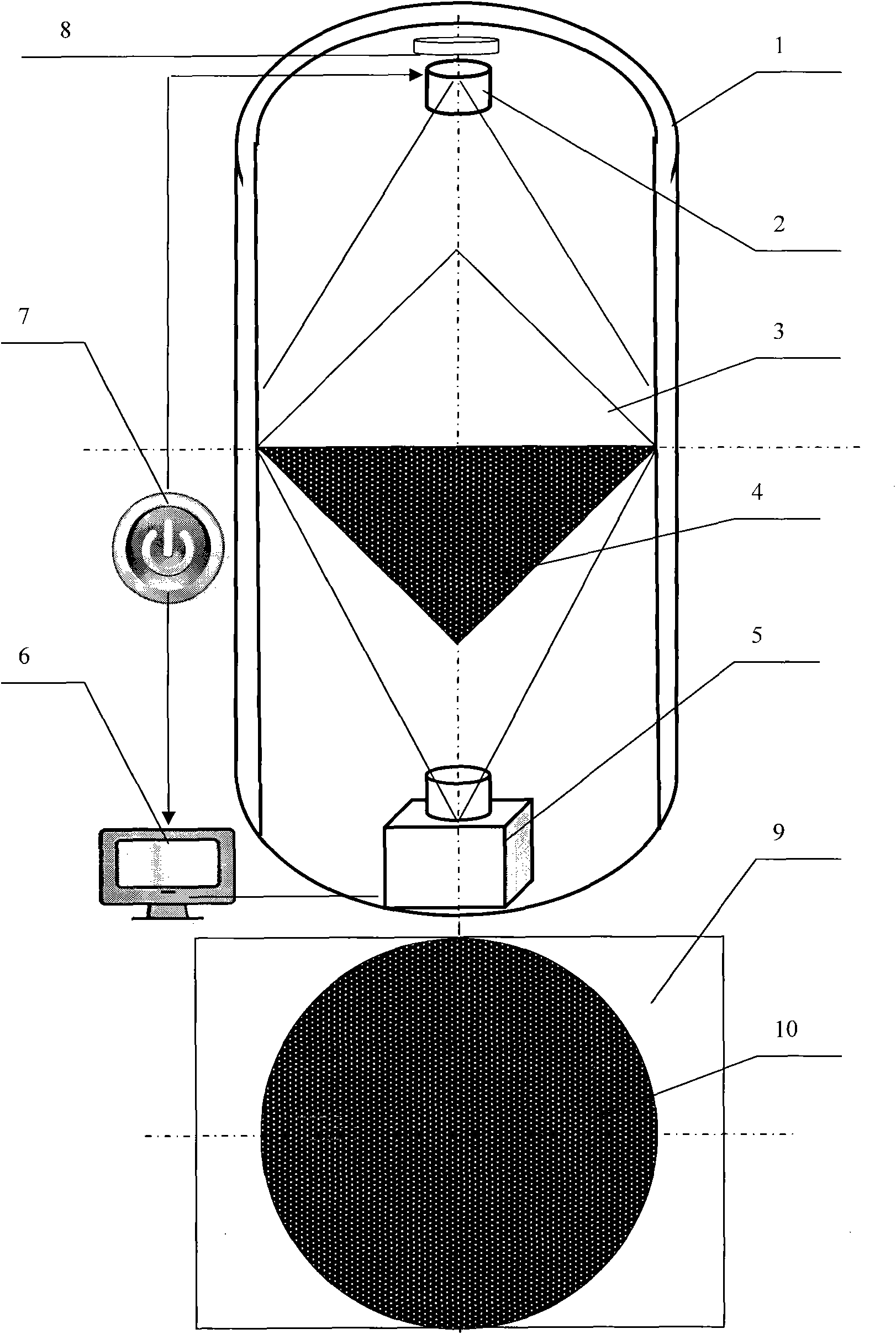
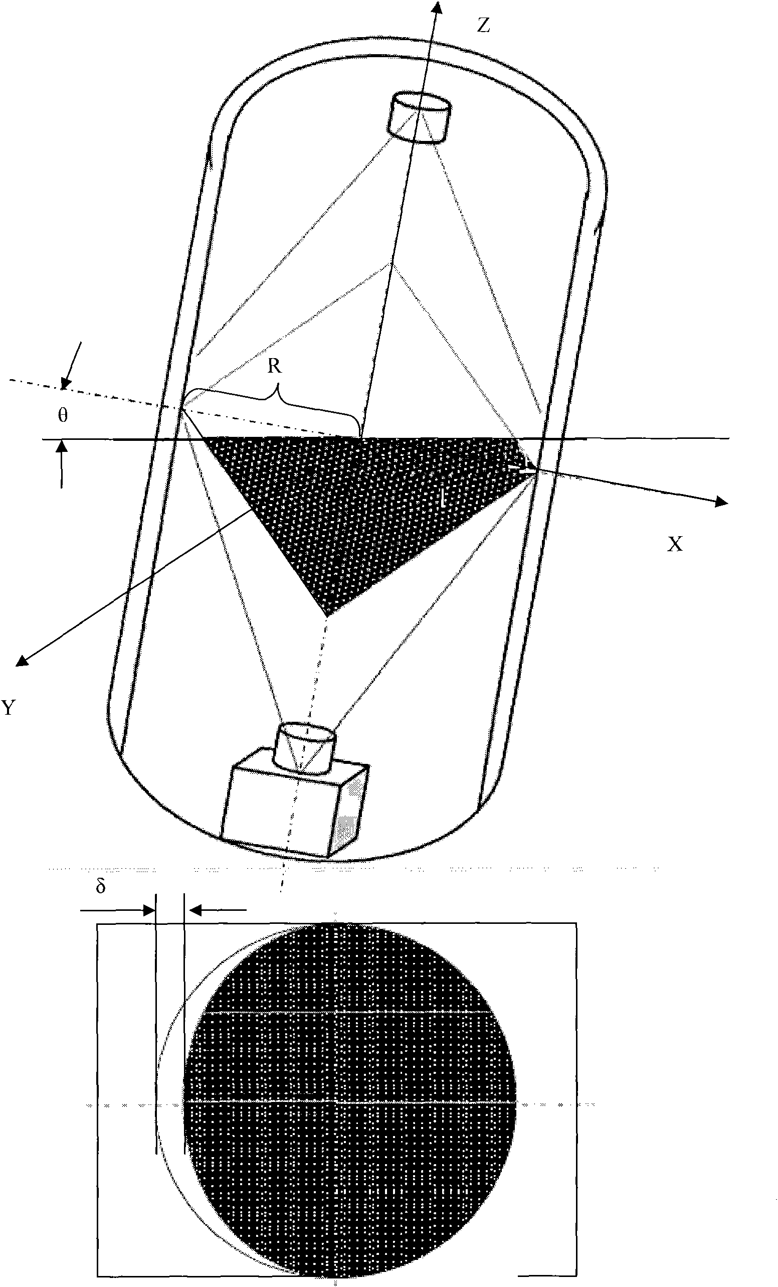
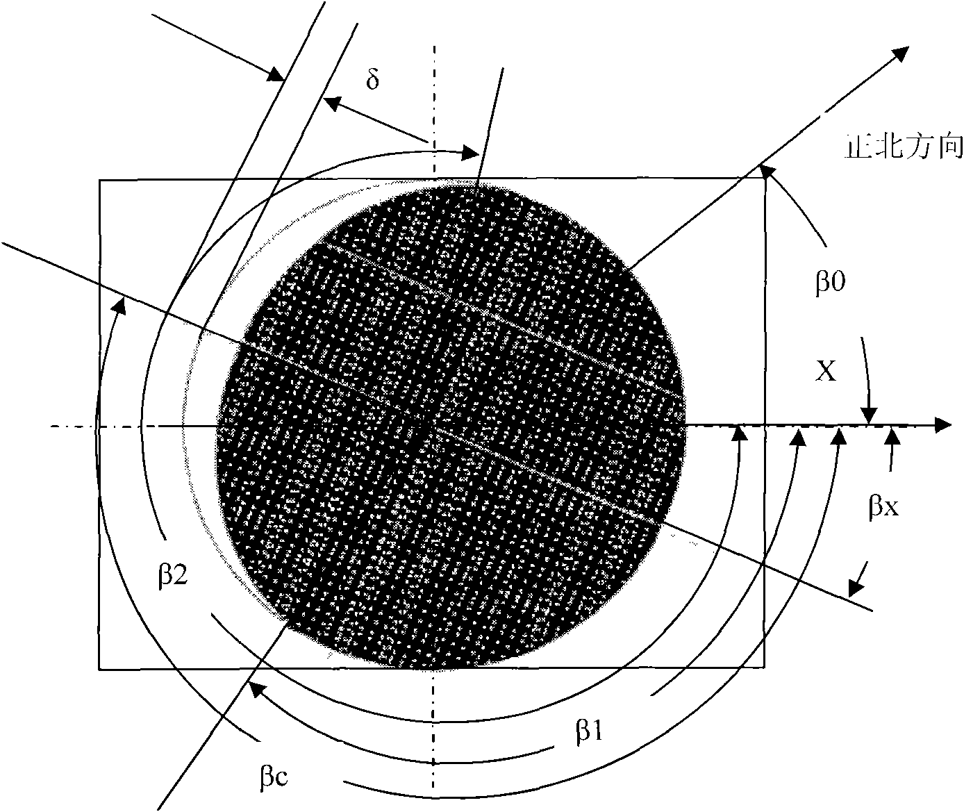

Image

  • Omnibearing tilt sensor based on machine vision
  • Omnibearing tilt sensor based on machine vision
  • Omnibearing tilt sensor based on machine vision

Examples


Embodiment 1

[0070] refer to Figure 1 to Figure 10 ,

[0071] An omnidirectional tilt sensor based on machine vision, including an omnidirectional tilt sensor housing 1, an LED lighting source 2, a transparent cone container 3, an opaque liquid 4, a camera 5, an embedded system 6, a power supply 7 and a compass 8, Described power supply 7 supplies power to described lighting source 2 and described embedded system 6, and described embedded system 6 supplies power to described camera 5 through USB interface, and described transparent cone container 3 is made of Two cones of the same size are combined into a closed container in a back-to-back manner; the transparent cone container 3 is fixed in the middle of the omni-directional tilt sensor housing 1, the LED lighting source 2 is fixed in the upper part, and the LED lighting source 2 is fixed in the lower part. The camera 5 is fixed; the LED lighting source 2 emits white light facing the center of the transparent cone container 3 downwards,...


PUM


Abstract

The invention relates to an omnibearing tilt sensor based on machine vision, comprising an omnibearing tilt sensor outer case, an LED (Light Emitting Diode) lighting source, a transparent cone container, light-proof liquid, a camera, an embedded system, a power source and a compass, wherein the transparent cone container is a closed container combined by two cones of the same size in a back to back mode; and the light-proof liquid is filled in the container, and the volume of the light-proof liquid is one half of the volume of the container. The light permeable part of the cone container is shot by a front body through the camera in the machine vision mode for analysis, judgement and calculation, and measurement parameters of measured objects, such as tilt angles, tilt azimuth angles, and the like, are obtained. The invention provides the omnibearing tilt sensor based on machine vision with the advantages of simple maintenance and adjustment, high measurement precision, wide measurement range, low manufacture cost, and strong real-time performance and safety as well as reliability.

Description

technical field [0001] The invention relates to a level detection device, which belongs to the application of physics, digital image processing technology, LED technology, embedded technology, network communication technology, level visualization technology and mechanical design technology in level detection, and is mainly suitable for bridge erection, railway Laying, civil engineering, oil drilling, aviation and navigation, industrial automation, intelligent platform, machining and other fields. Background technique [0002] At present, spirit levels can be mainly divided into two types: traditional spirit levels and electronic spirit levels; traditional spirit levels are mainly composed of carriers and straight level tubes. Put the spirit level on the surface of the object to be measured, and the air bubbles in the straight horizontal tube will run to the end at a high level, thus displaying the level / inclination state of the object. This bubble-type level has the followi...

Claims


Application Information

Patent Timeline
IPC IPC(8): G01C9/18G01C9/06
Inventor 汤一平王颖汤晓燕俞立宋鉷
Owner ZHEJIANG UNIV OF TECH
Learn More