Bidirectional light receiving and transmitting submodule

A sub-module, two-way optical technology, applied in the direction of electromagnetic transceiver, optical waveguide coupling, electromagnetic wave transmission system, etc., can solve the problems of optical filter 24 displacement, optical component interference, optical signal leakage, etc., to improve coupling optical Efficiency, increased reliability, reduced number of effects

Inactive Publication Date: 2010-12-01
IND TECH RES INST
View PDF2 Cites 13 Cited by
  • Summary
  • Abstract
  • Description
  • Claims
  • Application Information

AI Technical Summary

Problems solved by technology

As shown in the figure, in the filter assembly structure 2, each filter 24 is combined with its fixing seat 28 in a single-sided sticking manner. If encountering environmental changes, such as temperature changes or vibrations, each filter in this design The mirror 24 is extremely prone to displacement, deformation or even falling off
[0006] In the design of the existing optical transceiver components, due to the lack of tight connection between the components, the optical signal is easy to leak out of the unsealed joint gap, so the problem of mutual interference between the optical components is more serious

Method used


Image

  • Bidirectional light receiving and transmitting submodule
  • Bidirectional light receiving and transmitting submodule
  • Bidirectional light receiving and transmitting submodule

Examples


Embodiment 1

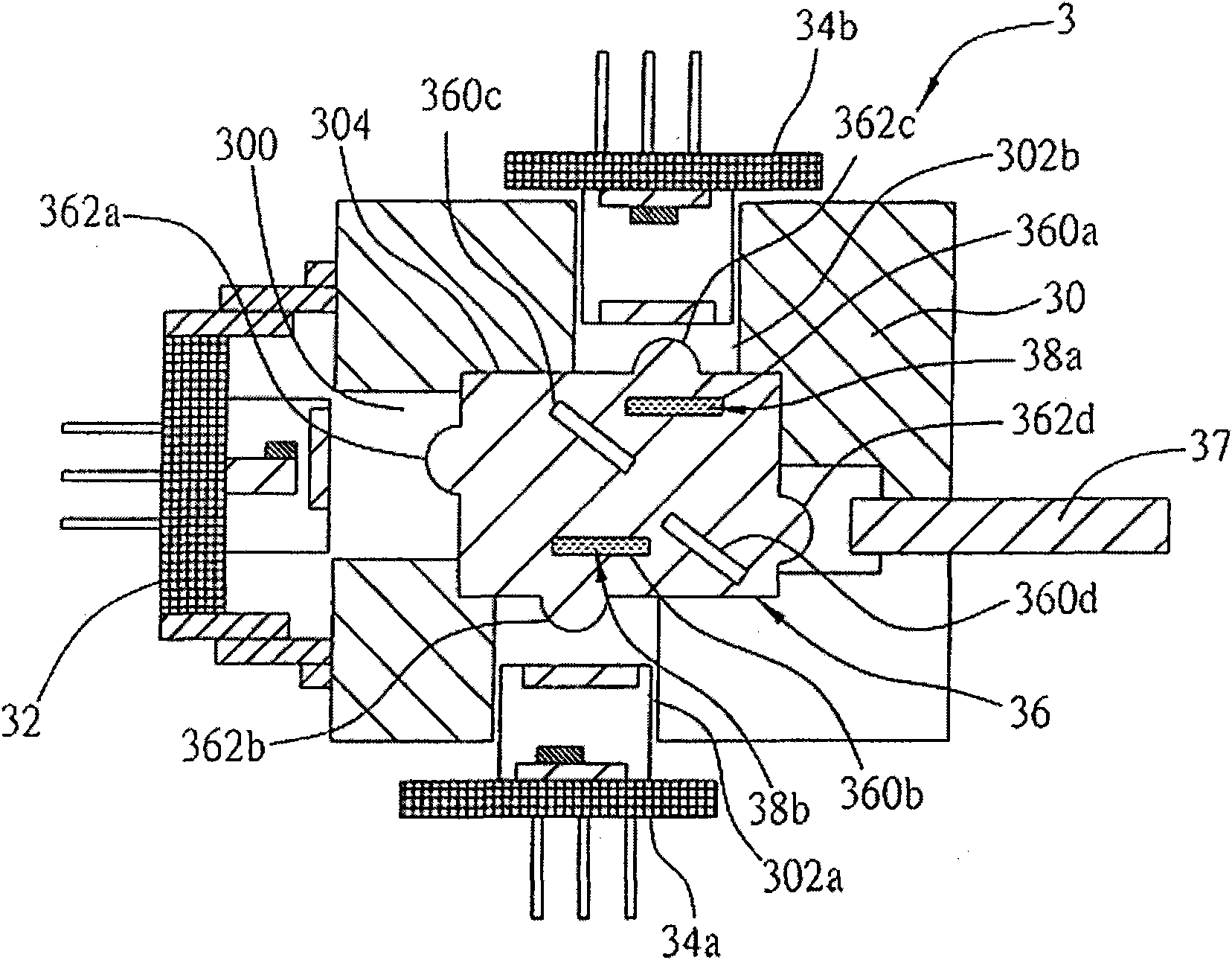
[0026] image 3 It is a sectional view of Embodiment 1 of the present invention. As shown in the figure, the bidirectional optical transceiver sub-module 3 of the present invention includes a housing body 30 and a housing space 304 . Wherein, the receiving body 30 has inside: a first opening 300 for connecting the light-emitting element 32 ; second openings 302 a and 302 b for connecting the light-receiving elements 34 a and 34 b respectively;

[0027] Wherein, the light-emitting element 32 in the first embodiment is used to send an optical signal to the light-conducting element 37 . Wherein, the light emitting element 32 is a laser diode (LD, Laser Diode), and the light conducting element 37 is an optical fiber.

[0028] The light receiving elements 34 a and 34 b are used to receive the light signal transmitted from the light conducting element 37 .

[0029] The carrier 36 is made of a light-transmitting material and has four grooves 360a, 360b, 360c and 360d, and the groo...

Embodiment 2

[0033] Figure 4 It is a sectional view of Embodiment 2 of the present invention. Compared with Embodiment 1, the four grooves 360a', 360b', 360c' and 360d' of the carrier 36 are combined with filters 38c, 38d, 38e and 38f. According to the general optical principle, this embodiment Example 2 can also achieve the same effect as Embodiment 1 of the present invention, and its optical signal transmission path is as follows: Figure 5A and Figure 5B shown, where Figure 5A Indicates the conduction path of the optical signal emitted by the light emitting element 32, Figure 5BIndicates the conduction path of the optical signal output by the light conduction element 37, Figure 5A and Figure 5B The function, detailed implementation and optical signal transmission mode of the display element can be easily deduced from Embodiment 1 and the optical principle.

[0034] Figure 6 It is a three-dimensional exploded view of Embodiment 2 of the present invention. It can be seen fr...


PUM


Abstract

The invention discloses a bidirectional light receiving and transmitting submodule which at least comprises a light-emitting component, at least one light receiving component and a load bearing component, wherein the load bearing component is provided with at least two grooves; at least one groove is combined with a filter lens; a light signal output by the light-emitting component is refracted by the filter lens and reflected by the groove, which is not combined with a filter lens, to a light conduction component; and the light signal, which is transmitted and output by the light conduction component, is reflected by the groove, which is not combined with the filter lens, and refracted by the filter lens to the light receiving component. The bidirectional light receiving and transmitting submodule realizes accurate optical contraposition through the modular structure design, relatively enhances the reliability of the optical components, reduces the number of used components, lowers the production cost, simplifies the production process, and can enhance the coupling efficiency by integrating the double-lens structure.

Description

[0001] This application is a divisional application with the application number 200510103169.0, the application date is September 20, 2005, and the invention name is "two-way optical transceiver sub-module". technical field [0002] The invention relates to an optical transceiver module, in particular to an optical transceiver sub-module for wavelength multi-task bidirectional transmission applied in an optical communication access network. Background technique [0003] Optical transceivers convert optical signals from optical fibers into electrical signals, or convert electrical signals into optical signals for optical fiber transmission. With the rapid development of the optical communication industry, the bidirectional multi-task optical transmission network has become the mainstream of the optical communication industry. The so-called two-way multitasking transmission network is to use a wavelength multiplexer to integrate two original independent transmission and receiv...

Claims


Application Information

Patent Timeline
Patent Type & Authority Applications(China)
IPC IPC(8): G02B6/42H04B10/24H04B10/40
Inventor 李俊兴陈逸明李欣哲余昱辰徐志豪李顺天
Owner IND TECH RES INST
Why Eureka
Try Eureka