Cycle-by-cycle current-limiting protection method for VIENNA rectifier and device thereof
A wave-by-wave current limiting and rectifier technology, which is applied in the direction of output power conversion device, AC power input conversion to DC power output, electrical components, etc., can solve the problem of power switch tube damage, complex control method, and influence on input side grid current distortion Performance indicators and other issues, to achieve the effect of continuous change of input current and improve reliability
- Summary
- Abstract
- Description
- Claims
- Application Information
AI Technical Summary
Problems solved by technology
Method used
Image
Examples
no. 1 example
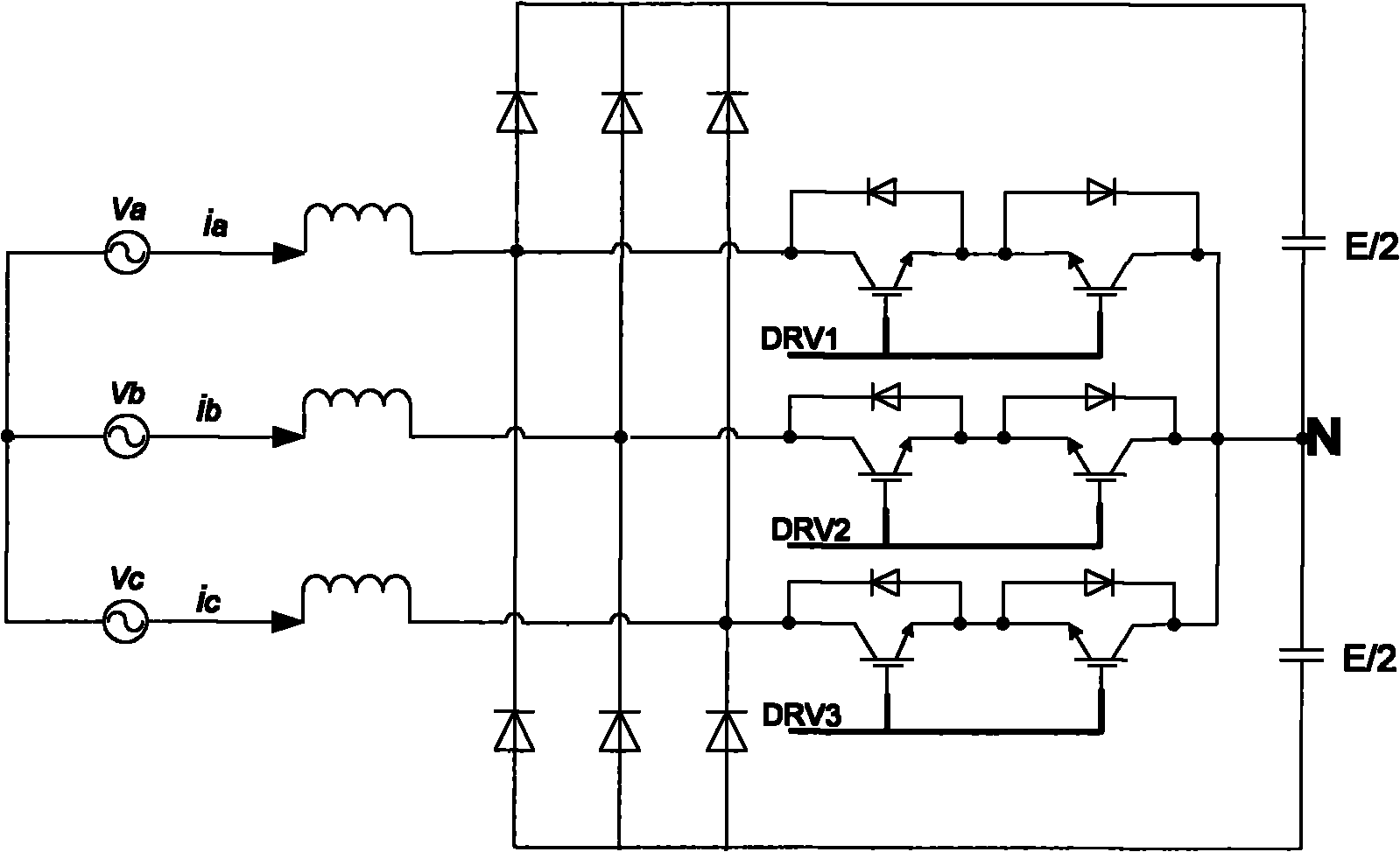
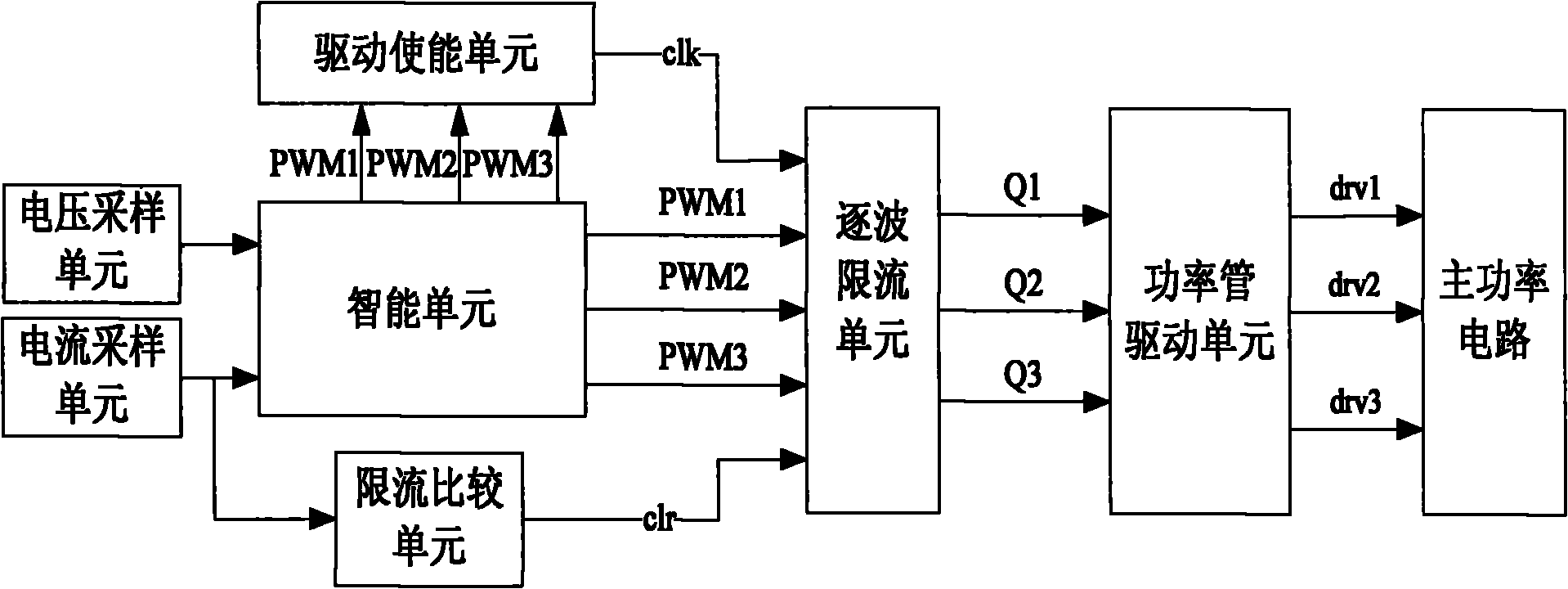
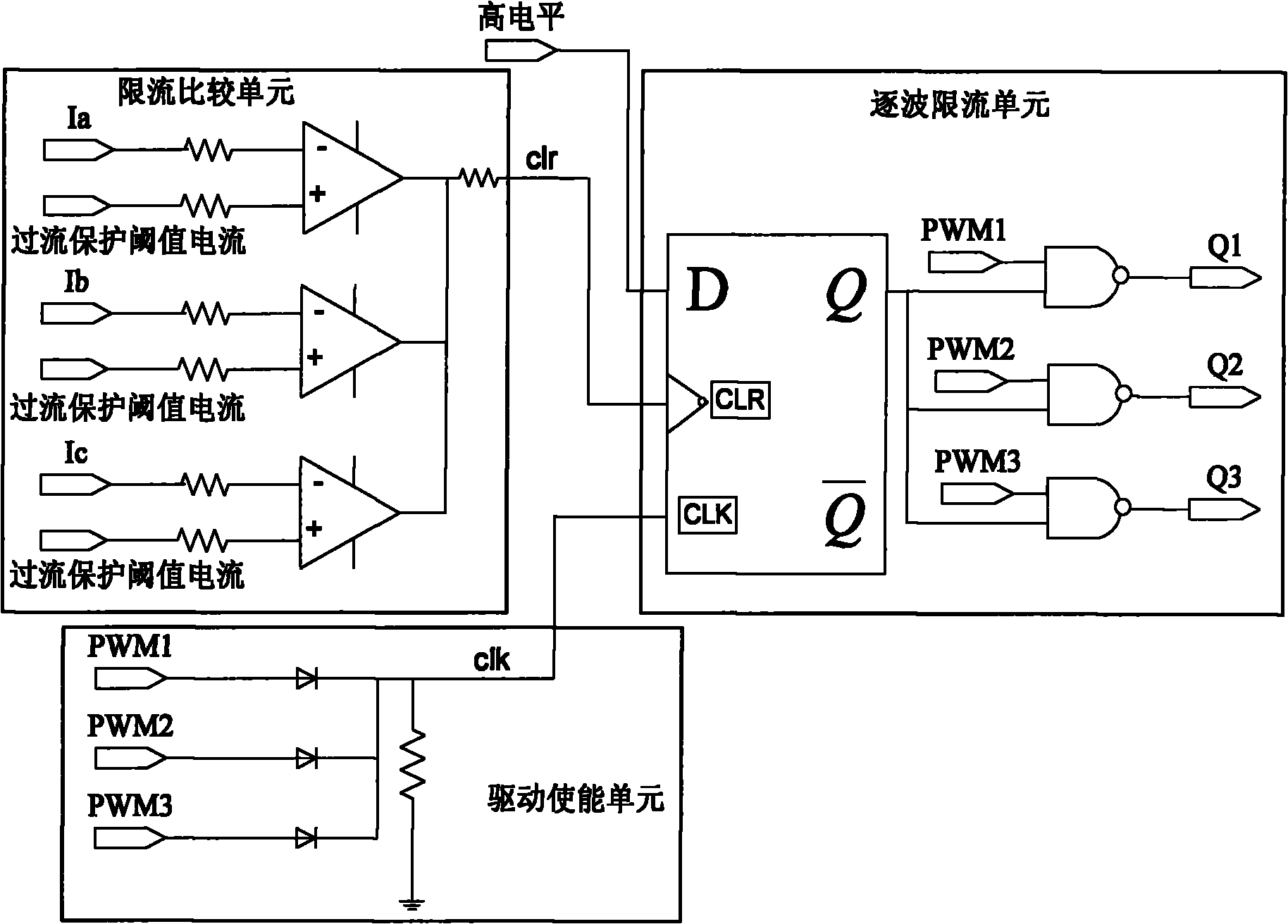
[0041] In the first embodiment of the present invention, a VIENNA rectifier wave-by-wave current limiting protection device, the connection relationship with the existing main power circuit switch tube drive circuit is as follows figure 2 shown. This device includes: drive enabling unit, wave-by-wave current limiting unit and current limiting comparison unit, such as image 3 As shown, among them,
[0042] 1) The current limiting comparison unit is connected to the output of the current sampling unit, and is used to generate a wave-by-wave current limiting enable signal according to the three-phase input current collected by the current sampling unit and output it to the wave-by-wave current limiting unit;
[0043]The current-limiting comparison unit specifically includes three comparators, and the three-phase input voltages: Ia, Ib and Ic are respectively input to the negative input terminals of the three comparators, and the overcurrent protection threshold current is conn...
no. 2 example
[0055] The second embodiment of the present invention, a device for wave-by-wave current limiting protection of a VIENNA rectifier, is substantially the same as the first embodiment, the only difference being that the composition and connection mode of the drive enabling unit are different. In this embodiment, the drive enabling unit includes two cascaded OR gates, such as Image 6 As shown, the first drive control signal PWM1 and the second drive control signal PWM2 are input to the two input terminals of the first OR gate 1, and the two output terminals of the first OR gate 1 are combined into a channel connected to the second OR gate 2 One input terminal, the third drive control signal PWM3 is input to the other input terminal of the second OR gate 2, and finally the second OR gate 2 outputs the wave-by-wave driving enable signal clk to the wave-by-wave current limiting unit.
no. 3 example
[0056] The third embodiment of the present invention, this embodiment is a method of wave-by-wave current limiting protection for VIENNA rectifiers summarized on the basis of the first and second embodiments, specifically including:
[0057] When the three-phase input current of the main power circuit exceeds the overcurrent protection threshold current for a certain period of time within a switching cycle, the switching tube of the main power circuit is stopped from being driven. The certain period of time may be 9 to 15 nanoseconds.
[0058] When the three-phase input current of the main power circuit falls back to the overcurrent protection threshold current and below, and the switching tube driving control signal reaches stability within one switching cycle, the switching tube of the main power circuit is re-driven.
[0059] Such as Figure 4 As shown, the stability of the switch tube driving control signal within one switching cycle means that the duration between the fi...
PUM
 Abstract
Description
Claims
Application Information
 - R&D
- Intellectual Property
- Life Sciences
- Materials
- Tech Scout
- Unparalleled Data Quality
- Higher Quality Content
- 60% Fewer Hallucinations
Browse by: Latest US Patents, China's latest patents, Technical Efficacy Thesaurus, Application Domain, Technology Topic, Popular Technical Reports.
© 2025 PatSnap. All rights reserved.Legal|Privacy policy|Modern Slavery Act Transparency Statement|Sitemap|About US| Contact US: help@patsnap.com


