Method for estimating rotor position of switched reluctance motor without position sensor

A technology of switched reluctance motor and sensor rotor, which is applied in the direction of electronic commutator, electronic commutation motor control, electrical components, etc. It can solve the problems of complicated preparation work, poor portability, and many error sources of the algorithm, and achieve universality Strong, simple to implement, easy to implement effects

Inactive Publication Date: 2010-12-01
NANJING UNIV OF AERONAUTICS & ASTRONAUTICS
View PDF4 Cites 26 Cited by
  • Summary
  • Abstract
  • Description
  • Claims
  • Application Information

AI Technical Summary

Problems solved by technology

[0005] To overcome the problems of the traditional relative positionless algorithm based on flux linkage or inductance, the preparation work is complex, the algorithm has many error sources, and the portability is poor, and a simple, easy-to-implement, and versatile position sensorless position estimation strategy is obtained

Method used


Image

  • Method for estimating rotor position of switched reluctance motor without position sensor
  • Method for estimating rotor position of switched reluctance motor without position sensor
  • Method for estimating rotor position of switched reluctance motor without position sensor

Examples


Embodiment Construction

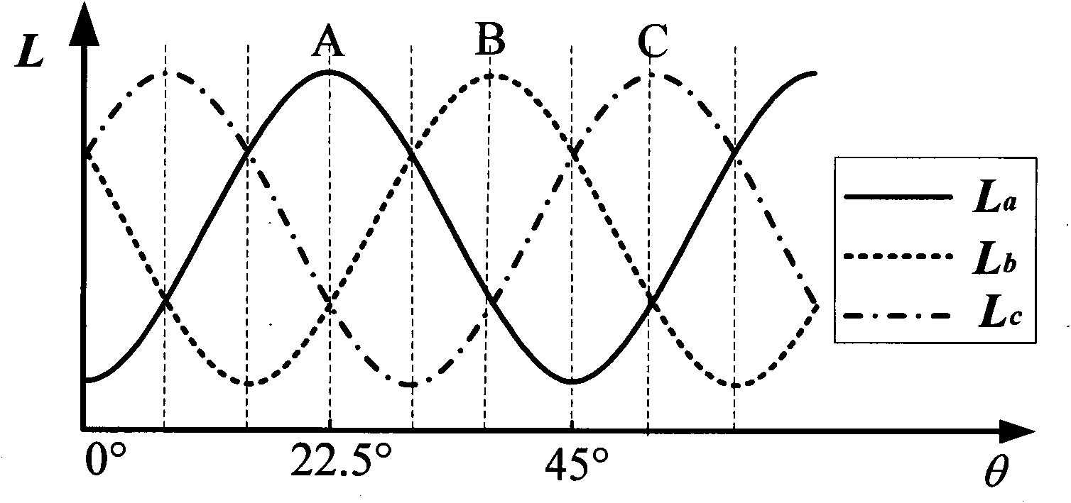
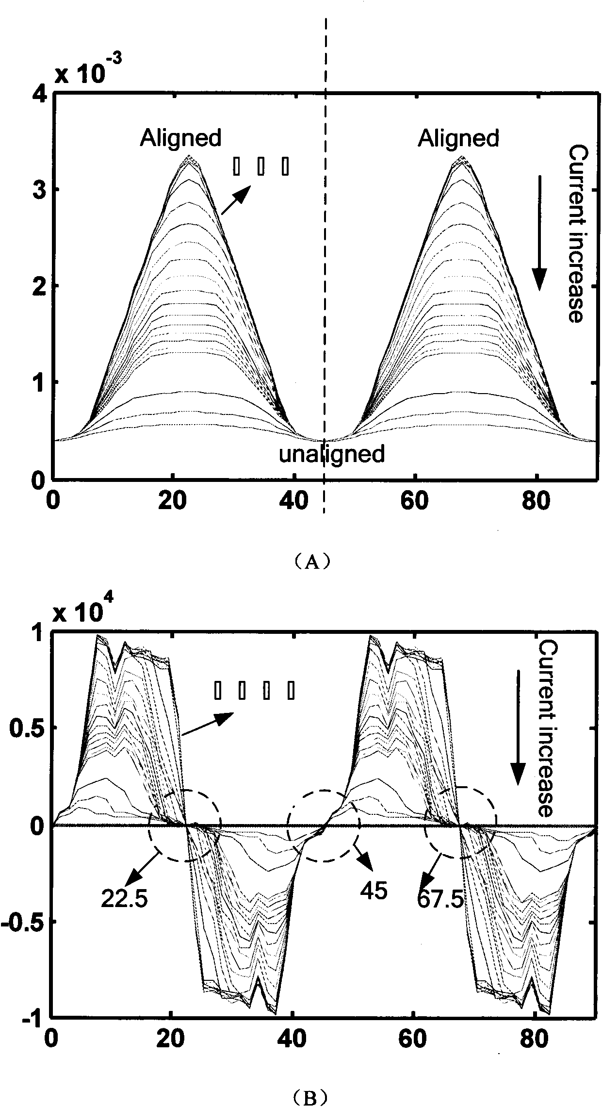
[0026] The invention utilizes the relationship between inductance and rotor position, and estimates the rotating speed and rotor position information by detecting the maximum inductance position point in each period.

[0027] Below in conjunction with accompanying drawing, the technical scheme of invention is described in detail:

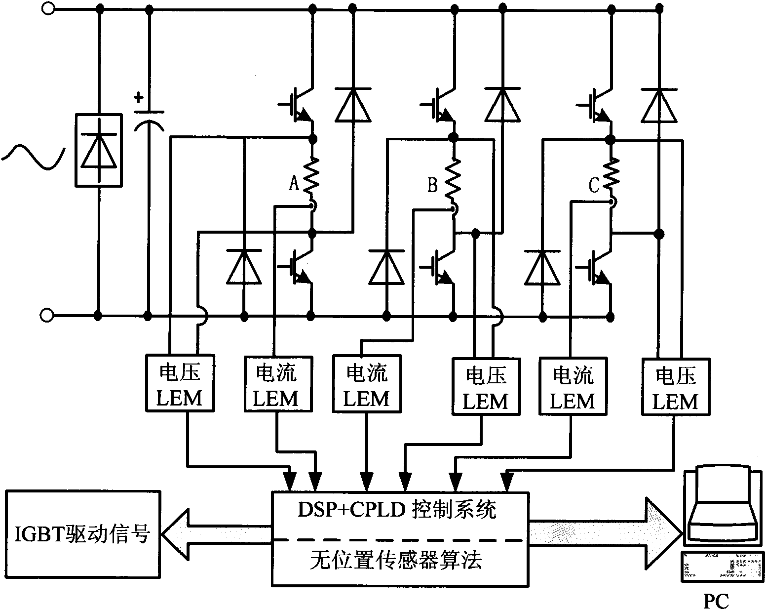
[0028] figure 1 A block diagram of a switched reluctance motor speed control system. The switched reluctance motor speed control system is mainly composed of a switched reluctance motor (SRM), a power converter, a control system (DSP+CPLD), a position sensor, and a voltage and current detection and protection circuit. Among them, the controller is the core of the system, which collects, calculates and processes the detection signal, completes the relevant control algorithm, and outputs the corresponding control signal. The inductance calculation and the algorithm of the position sensorless technology in the present invention are all completed by t...


PUM


Abstract

The invention discloses a method for estimating the rotor position of a switched reluctance motor without a position sensor, and belongs to the technical field of the control of the switched reluctance motors. In the method, based on the fundamental feature that an inductor of the switched reluctance motor is changed periodically with the rotor position, phase inductance reaches maximum at a position where a stator is aligned with a rotor, so the slope of the phase inductance is changed into negative from positive at the maximum position of the inductance, and slope zero-crossing points exist. In the method, by sampling each phase current and phase voltage in real time, each phase inductance value can be detected in real time, and simultaneously, the inductance slope can be calculated; the calculated inductance slope is subjected to zero balancing to obtain pulse signals of the slope zero-crossing points, so that a zero-crossing position, namely the position where a stator tooth pole is aligned with a rotor tooth pole can be detected; and the phase difference of the two adjacent maximum inductance positions is 45 degrees, so the difference of positions of the two slope zero-crossing points is 1/8 cycle, and the real-time rotate speed and rotor position information of the motor can be calculated according to the zero-crossing pulse signals. The method has the advantages of independent of parameters of a motor body, no need of measurement of motor characteristics such as static flux linkage and the like, simple algorithm and easy realization, so the method has strong generality compared with a non-position strategy.

Description

technical field [0001] The invention relates to a position sensorless rotor position estimation method of a switched reluctance motor, which belongs to the technical field of switched reluctance motor control. Background technique [0002] Switched Reluctance Motor (SRM), as a new type of speed control system, not only has the basic advantages of AC and DC speed control, but also has unique high-speed performance and fault tolerance. This makes it widely concerned in the field of AC and DC drives in aerospace and various civil manufacturing industries, and undoubtedly has a good application prospect and market value. For switched reluctance motor systems, real-time and accurate rotor position information is a prerequisite for reliable operation and high-performance control. In current practical applications, shaft position sensors or other detecting position detectors are generally used to obtain position information, which not only increases the cost and complexity of the ...

Claims


Application Information

Patent Timeline
Patent Type & Authority Applications(China)
IPC IPC(8): H02P6/18H02P6/185
Inventor 蔡骏邓智泉周竟成
Owner NANJING UNIV OF AERONAUTICS & ASTRONAUTICS
Why Eureka
Try Eureka