
Gob-side road retaining supporting method and road-injecting slip mould

A technology of sliding form and injection roadway, which is applied in the direction of earthwork drilling, pillar/bracket, wellbore lining, etc. It can solve the problems of not being able to move as a whole, and achieve the effect of easy transportation and use, simple structure and strong applicability

Active Publication Date: 2010-12-08
兖矿能源集团股份有限公司
View PDF2 Cites 25 Cited by
  • Summary
  • Abstract
  • Description
  • Claims
  • Application Information

AI Technical Summary

Problems solved by technology

[0004] In order to overcome the above-mentioned deficiencies in the prior art that the filling mold needs to be disassembled and cannot be moved as a whole, and the support and temporary support of the filling wall next to the pouring roadway and the side of the goaf need to be strengthened, the present invention provides a gob-side retaining support method, it can save the filling mold assembly and disassembly process, and the overall pulling; when pouring the filling wall next to the roadway, add temporary support to the side of the goaf, so that the construction is safe; support, more effectively control the delamination of the direct roof

Method used


Image

  • Gob-side road retaining supporting method and road-injecting slip mould
  • Gob-side road retaining supporting method and road-injecting slip mould
  • Gob-side road retaining supporting method and road-injecting slip mould

Examples


Embodiment Construction

[0031] The present invention will be further described below in conjunction with drawings and embodiments.

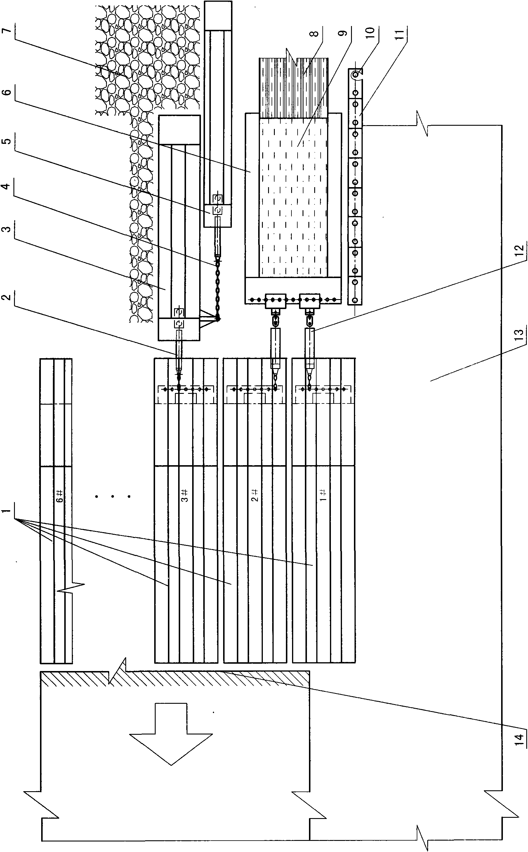
[0032] exist figure 1 Fig. 1 shows the arrangement of the entry slip form 6, bunker brackets 3 and 5, head bracket 1 and other equipment in the gob-side entry retaining support method of the present invention at the lower end of the fully mechanized mining face.

[0033] The gob-side entry retaining support method of the present invention is to move along with the fully mechanized mining face, after the header support 1, transport the goaf 7 side of the trough 13, use the concrete pump to transport the concrete long-distance through the pipeline, and pour it to the filling mold , the filling concrete 9 in the filling mold is solidified, and the roadside filling wall 8 (or the roadside filling body) is constructed to form the roadside support belt. Maintain the transport chute in the previous section and use it as the return air chute in the lower section.

[0034] For...


PUM


Abstract

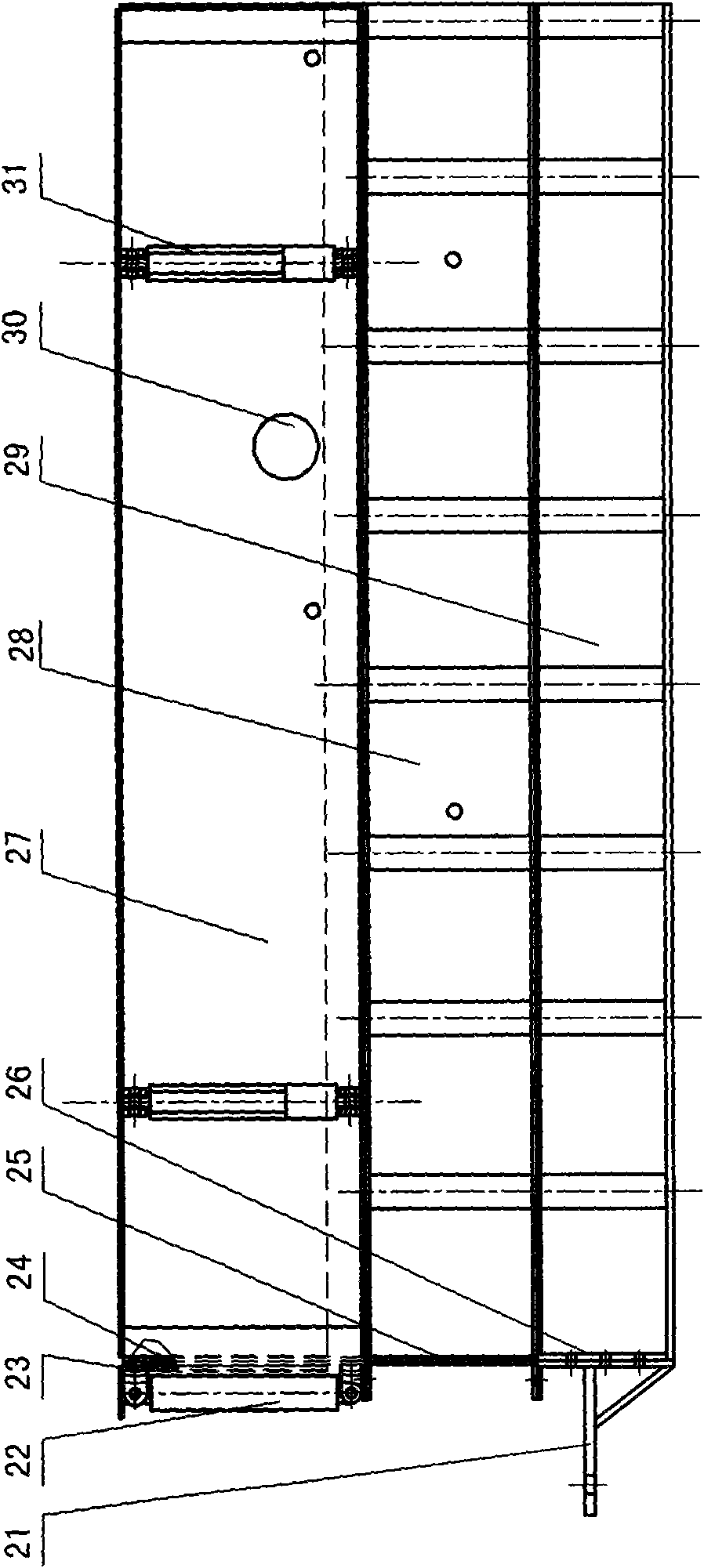
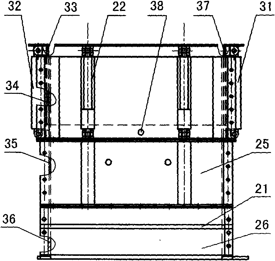
The invention relates to a gob-side road retaining supporting method of mining roadways of coal mines, comprising the following steps of: feeding a concrete to a filling mould by using a pump to pour along the lapse of a working surface on a gob side of the gob-side road retaining, and constructing a roadside backfilling wall 8; supporting top plates arranged above the backfilling wall 8 and outside the backfilling wall 8 by using an anchor cable and constructing in the front side of a leading support 1; adopting a height-adjustable integral pull-shift type road-injecting slip mould 6 by the backfilling mould; using blindage supports 3 and 5 on one side of the gob of the road-injecting slip mould to temporarily support; connecting the road-injecting slip mould and the blindage supports with the leading support 1 through a pull-shift jack to shift; and enabling the blindage supports, the roadside backfilling wall and the top surfaces of each leading support supported by the external anchor cable to be provided with grooves for protecting anchor cables of anchor rods. Besides the advantages of digging less roads, realizing pillarless exploration, releasing the tension of mining drifting and the like, the invention also has the advantages that the height of the road-injecting slip mould is integrally regulated by means of integral pull-shift hydraulic, the road-injecting slip mould is convenient to use and the work efficiency is improved; the supporting of the anchor cable is matched with the supporting of the backfilling wall to effectively control a separation layer of an immediate roof, and the blindage supports and the leading support can protect the anchor cables and the anchor rods from being jacked broken so as to lose efficacy.

Description

technical field [0001] The invention relates to a gob-side entry support technology of a coal mine recovery roadway, in particular to a gob-side entry support method in which the side of a gob-side entry is supported by a concrete pouring side filling wall. The utility model also includes a filling mold slip form for filling a wall next to a concrete pouring road. Background technique [0002] In order to reduce the loss of coal pillars between the transportation lane and the return airway in the coal mining section, coal pillarless mining is adopted, that is, it is close to the goaf, and the transportation channel of the previous section is reserved and maintained as the return air of the lower section Along the trough, no coal pillars are left in between, which saves the process of digging a roadway for the mining of the next working face. In order to achieve the above purpose, it is necessary to strengthen the support on the side of the goaf behind the support while mini...

Claims


Application Information

Patent Timeline
IPC IPC(8): E21D15/02E21F15/00E21D11/10
Inventor 黄福昌林东才倪兴华李树荣史守忠赵志征轩涛
Owner 兖矿能源集团股份有限公司
Learn More