Energy conversion hydraulic plant and method for controlling such plant

An energy conversion and hydraulic technology, used in pump control, mechanical equipment, hydropower, etc., can solve the problems of inconsistent shape and flow direction, incomplete filling of guides, separation of guide surfaces, etc., to optimize performance , Improve the stability, reduce the effect of fluid loss

Inactive Publication Date: 2014-07-02
GE RENEWABLE TECH
View PDF10 Cites 0 Cited by
  • Summary
  • Abstract
  • Description
  • Claims
  • Application Information

AI Technical Summary

Problems solved by technology

Therefore, this reduces the efficiency of the device
[0004] Furthermore, in equipment with a downstream flow channel—sometimes referred to as a "suctioner" because of its shape and direction of flow—it sometimes happens that the forced flow does not completely fill the Separation of the flow relative to the surface of the channel

Method used


Image

  • Energy conversion hydraulic plant and method for controlling such plant
  • Energy conversion hydraulic plant and method for controlling such plant
  • Energy conversion hydraulic plant and method for controlling such plant

Examples


Embodiment Construction

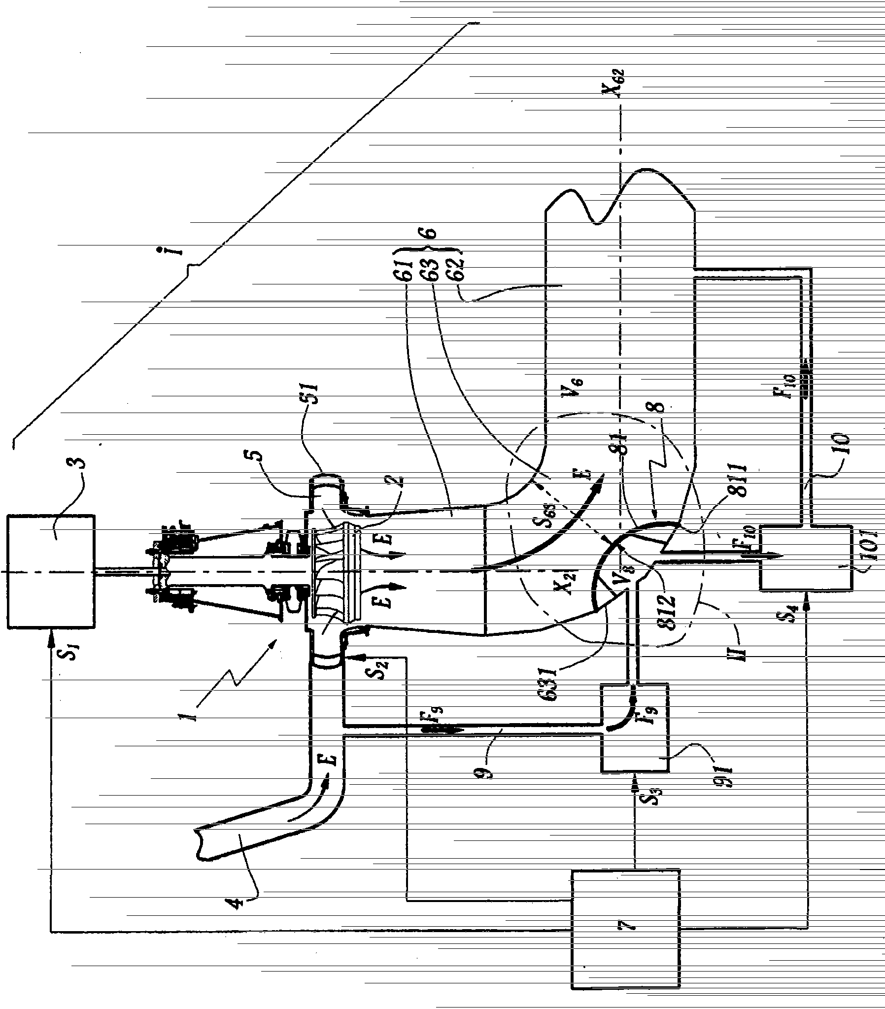
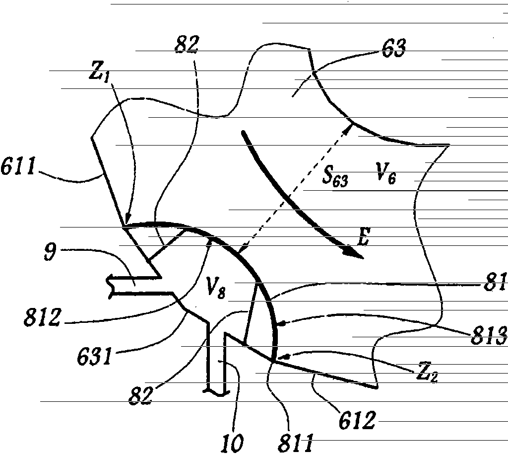
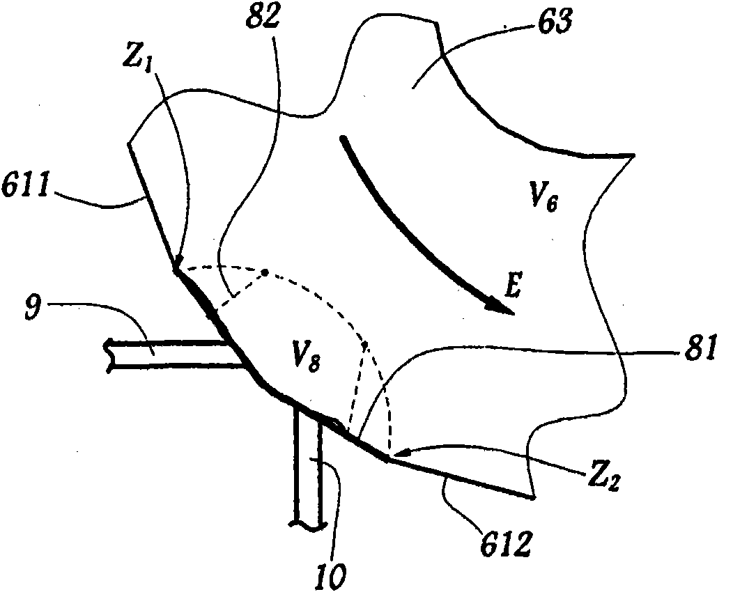
[0029] Figures 1 to 3 The plant I shown has a Francie-type turbine 1 whose wheel 2 is intended to be driven in rotation by a forced flow E from a reservoir not shown. The wheel body 2 constitutes a rotating part of the turbine 1 . The turbine 1 is connected to a generator 3 which, in response to the rotation of the wheel body 2, supplies alternating current to a grid not shown. Thus, the device I can convert the hydraulic energy of the flow E into electrical energy. The flow E is conveyed to the wheel body 2 by a forced channel 4 which extends between the water reservoir and a tank 5 equipped with guide vanes 51 which locally regulate the flow E. A channel 6 is provided downstream of the wheel body 2 for discharging the flow E downstream of the installation I and retransmitting it to the river from which it is drawn.

[0030] The components 4, 5 and 6 together define the hydraulic path of the flow E.

[0031] A control unit 7 is used to operate the turbine 1 , in particul...


PUM


Abstract

The invention relates to a hydrodynamic device (I) defining a path (4, 5, 6) of forced water flow (E), having at least one machine (1) of turbine, pump or turbopump type and a component (8) , said part (8) is provided with at least one deformable wall (81) defining at least one enclosed space (V8) of variable size. The device also has means (9, 91) for supplying (F9) pressurized fluid to the enclosed space. The part with deformable walls (81) is installed in a hydraulic channel (6) downstream of a rotating part (2) of the machine (1). The deformable wall locally defines an adjustable passage section (S63) of the flow (E) in the hydraulic channel (6) downstream of the rotating part (2). According to the method of the invention, the pressurized fluid is injected (F9) into a closed space (V8) of variable dimensions delimited by a part (8) arranged downstream of the rotating part (2) In a hydraulic channel (6), to adjust the passing section (S63).

Description

technical field [0001] The present invention relates to a hydraulic device for converting hydraulic energy into mechanical or electrical energy or vice versa, having a machine of the turbine, pump or turbopump type, and in said hydraulic conversion device is defined Create a hydraulic path for forcing water to flow. Background technique [0002] It is known to design such hydrodynamic installations according to a nominal operating point, which depends, for example, on the drop and power to be achieved at the output of the installation. In fact, the efficiency of a turbine and its dynamic performance are greatly influenced by hydraulic conditions, such as the height and flow of water passing through lakes and rivers near the location of the turbine, and by development needs which determine the amount of water passing through the turbine. However, the design of the different hydraulic channels of the plant, which is mainly suitable for one operating point, may not be suitable...

Claims


Application Information

Patent Timeline
Patent Type & Authority Patents(China)
IPC IPC(8): F03B3/06F03B3/14F03B3/18F03B15/04F03B11/00
CPCF03B3/02F03B11/04F03B3/186F03B11/002Y02E10/223Y02E10/226F04D15/0022Y02E10/20
Inventor M·H·库斯东M·萨布林
Owner GE RENEWABLE TECH
Why Eureka
Try Eureka