Self-assisted retractor for surgical operation

A technology of surgical operation and retractor, which is applied in the field of medical devices, can solve the problems that the pulling part cannot be moved arbitrarily at the bedside, occupies a large amount of operation space, and has a large number of parts, so as to achieve a clean and orderly operation environment and convenient operation , small size effect

Active Publication Date: 2010-12-15
JIANGSU HAIZE MEDICAL TECH DEV
View PDF4 Cites 4 Cited by
  • Summary
  • Abstract
  • Description
  • Claims
  • Application Information

AI Technical Summary

Problems solved by technology

[0003] The purpose of the present invention is to design a retractor for a series of problems such as small applicable range, large volume, large number of parts, occupying a lot of operating space, affecting the doctor's station operation, and the pulling part cannot be moved arbitrarily at the bedside. This kind of structure is simple, it can be applied to any part of the traction, small size, the device of pulling the hook plate is collected in a cylindrical shell, and the lifting rod fixing device is simple in structure, easy to operate, stable and reliable, and will not affect the surgeon Pull chain cord built-in surgical retractor operated in standing position

Method used


Image

  • Self-assisted retractor for surgical operation
  • Self-assisted retractor for surgical operation
  • Self-assisted retractor for surgical operation

Examples


Embodiment 1

[0033] Such as Figure 1-9 shown.

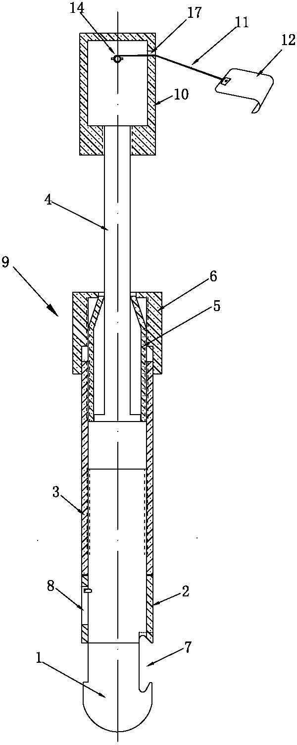
[0034] A retractor for self-service surgery, which is mainly composed of a lifting device 9, a belt receiving device 10, a traction belt 11 (which can be realized by using a nylon textile belt or a plastic braided belt with a width of about 1 cm) and a hook plate 12 compositions such as figure 1 As shown, the take-up device 10 is installed on the upper end of the lifting rod 4 in the lifting device 10, and the take-up device 10 is mainly composed of a housing 13, a telescopic take-up shaft 14 and a rocker arm 15, and the telescopic take-up shaft The main body of 14 is located in the housing 13, and the rocking arm 15 is connected with one end of the telescopic take-up shaft 14 and is positioned outside the housing 13. The housing 13 is provided with a groove 16 for accommodating the rocking arm 15, and one end of the traction belt 11 It is connected with the retractable take-up shaft 14, and the other end passes through the belt hole 17 on...

Embodiment 2

[0046] Such as Figure 1-8 , 10 shown.

[0047] The difference between this embodiment and Embodiment 1 is that the structure of the take-up shaft 14 is as follows: Figure 10 As shown, the take-up shaft is a fixed-length structure, and its two ends are all supported on the shell wall of the housing 13, and one of the ends stretches out of the housing 13 in order to facilitate the sleeve length of the rocker 15, and the stretched length should be the same as that of the rocker 15. The length that is sleeved on the take-up shaft 14 matches. The rocking wall 15 and the take-up shaft 14 of the present embodiment are movable connection structures. When in use, the rocking hand 15 is put on the take-up shaft 14 and extends out of one end of the housing 13 (the two can adopt a polygonal matching structure, and can also adopt a cylindrical hole. Pin or key matching structure), the position of the groove 16 can be slightly deviated when fitting, so as to avoid excessive insertion of...


PUM

PropertyMeasurementUnit
Widthaaaaaaaaaa

Abstract

The invention relates to a self-assisted retractor for surgical operation. The retractor is characterized by mainly comprises an elevating device (9), a belt withdrawing device (10), a traction belt (11) and a hook plate (12), wherein the belt withdrawing device (10) is arranged at the upper end of an elevating lever (4) in the elevating device (9) and mainly comprises a shell (13), a telescopic belt withdrawing shaft (14) and a rocker arm (15); the main body of the telescopic belt withdrawing shaft (14) is positioned in the shell (13); the rocker arm (15) is connected with one end of the telescopic belt withdrawing shaft (14) and positioned outside the shell (13); the shell (13) is provided with a groove (16) for accommodating the rocker arm (15); and one end of the traction belt (11) is connected with the telescopic belt withdrawing shaft (14), while the other end passes through a belt hole (17) on the shell (13) and is connected with the hook plate (12). The retractor has the advantages of simple structure, convenient manufacturing and use and low cost.

Description

technical field [0001] The invention relates to a medical device, especially a retractor used in surgery that can replace the manual retraction of the incision so that the operation field can be fully exposed, specifically a self-service retractor suitable for various operations. Surgical retractor. Background technique [0002] At present, in the operation of straight abdominal incision, such as general surgery, urology, obstetrics and gynecology, in order to obtain an ideal surgical field, it is necessary to keep the opened abdomen in a good retraction state; also in the operation of thorax, back and spine, etc. The incision also needs to be retracted. The existing method one is to rely on the surgical assistant to pull the incision apart from both sides with pull hooks, which is poor in effect and labor-intensive. People have invented various abdominal operation retractors to replace artificial traction for this reason, and people are liberated from heavy physical labor,...

Claims


Application Information

Patent Timeline
IPC IPC(8): A61B17/02
Inventor 钱建民
Owner JIANGSU HAIZE MEDICAL TECH DEV
Why Eureka
Try Eureka