
Light-emitting diode with gradually changed refractive index of light-emitting layer

A technology of light-emitting diodes and refractive index gradients, which can be applied to electrical components, circuits, semiconductor devices, etc., and can solve problems such as reducing luminous efficiency.

Inactive Publication Date: 2010-12-15
AQUALITE CO LTD
View PDF4 Cites 3 Cited by
  • Summary
  • Abstract
  • Description
  • Claims
  • Application Information

AI Technical Summary

Problems solved by technology

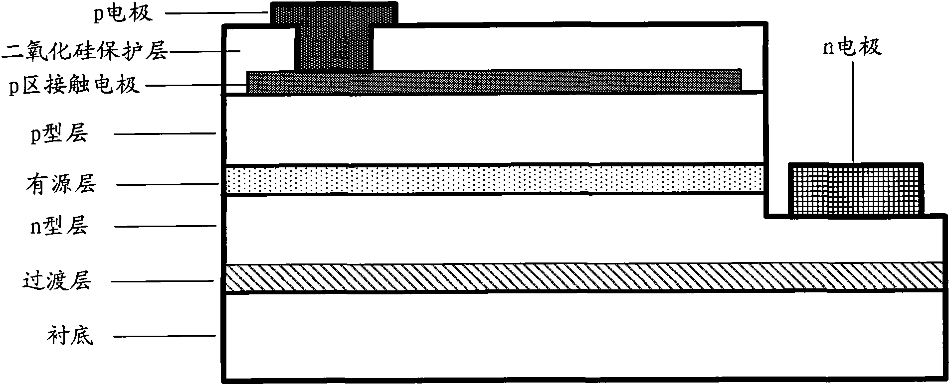
At the same time, in order to protect the light-emitting diode chip and reduce the leakage of the device, a protective layer, such as SiO2, will be deposited between the light-emitting diode and the packaging material. 2 ,like figure 1 shown, but SiO 2 The refractive index is about 1.46, which will reduce the luminous efficiency

Method used


Image

  • Light-emitting diode with gradually changed refractive index of light-emitting layer
  • Light-emitting diode with gradually changed refractive index of light-emitting layer
  • Light-emitting diode with gradually changed refractive index of light-emitting layer

Examples


Embodiment Construction

[0019] The principles and features of the present invention are described below in conjunction with the accompanying drawings, and the examples given are only used to explain the present invention, and are not intended to limit the scope of the present invention.

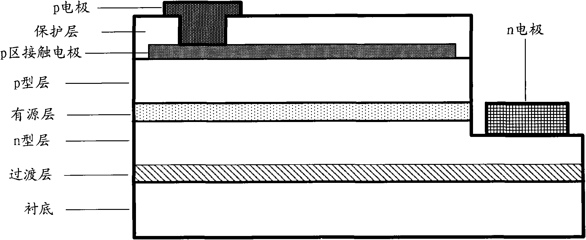
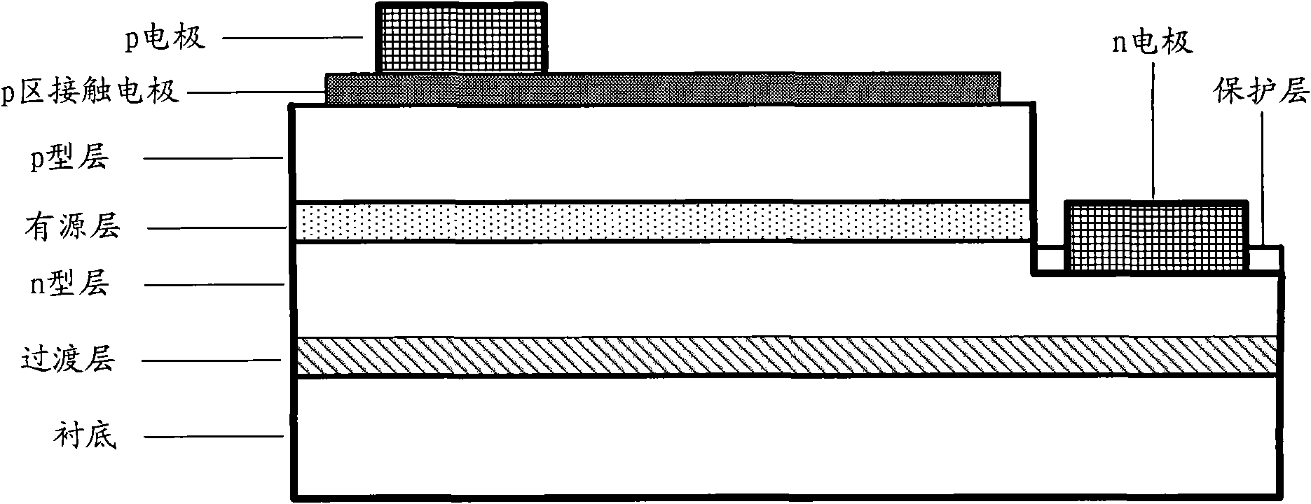
[0020] Such as figure 2 As shown, in the structure of Example 1, the light-emitting diode is a light-emitting diode with a lateral structure, including a substrate, and a transition layer, an n-type semiconductor layer, an active layer, a p-type semiconductor layer, and a p-type semiconductor layer formed sequentially on the substrate. The contact electrode layer, the p-electrode that is arranged on the p-region contact electrode layer, and the n-electrode on the n-type semiconductor layer electrode region of the n-type semiconductor layer are vacuum evaporated or electron beam evaporated or radio frequency (RF) sputtering ( sputtering) or plasma chemical vapor deposition (PECVD) to deposit a layer of material on t...


PUM


Abstract

The invention relates to a light-emitting diode with gradually changed refractive index of a light-emitting layer. The refractive index of the light-emitting layer is gradually changed by arranging a protective layer outside the light-emitting layer of the light-emitting diode, wherein the refractive index of the material of the protective layer is between that of the material of the light-emitting layer and that of the packaging material of the light-emitting diode. The luminescent efficiency of the light-emitting diode can be improved and the leakage rate of the light-emitting diode can be reduced.

Description

technical field [0001] The invention relates to the technical field of light-emitting diodes, in particular to a high-efficiency light-emitting diode with a gradient refractive index of a light-emitting layer that improves luminous efficiency. Background technique [0002] Due to the advantages of high efficiency, energy saving, and environmental protection, light-emitting diodes are gradually used in various fields such as lighting, transportation, communications, and backlights. [0003] The refractive index of the light-emitting layer material of the light-emitting diode is between 2.2 and 3.8, and the refractive index of the packaging material is about 1.5, which is obviously lower than the refractive index of the light-emitting diode material, which makes the light-emitting efficiency of the light-emitting diode very low. Say between 4% and 12%, most of the light is trapped inside the LED. At the same time, in order to protect the light-emitting diode chip and reduce t...

Claims


Application Information

Patent Timeline
IPC IPC(8): H01L33/56
Inventor 杨新民项艺易贤靳彩霞董志江
Owner AQUALITE CO LTD
Learn More