Acousto-optic modulation-based 2mu m polarized orthogonal laser emitting system applied to laser heterodyne interferometer
A technology of laser heterodyne interferometry and laser emission system, which is applied to lasers, phonon exciters, optical devices, etc., can solve the problem of low measurement accuracy of laser heterodyne interferometers, avoid beam energy loss, and improve measurement accuracy , the effect of improving the transmission efficiency
- Summary
- Abstract
- Description
- Claims
- Application Information
AI Technical Summary
Problems solved by technology
Method used
Image
Examples
specific Embodiment approach 1
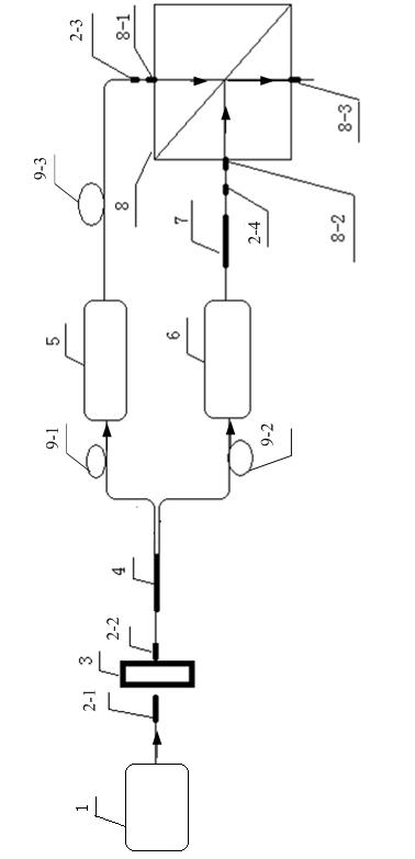
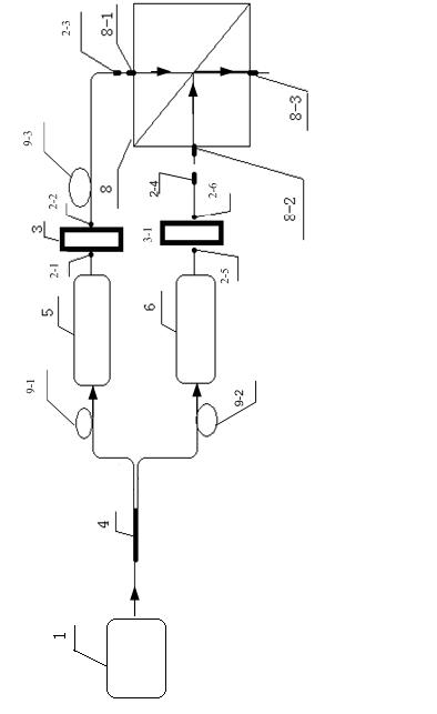
[0020] Specific implementation mode one: according to the instructions attached figure 1 , 2 , 3, 4, 5 and 6 specifically describe this embodiment, a 2 μm polarization orthogonal laser emission system based on acousto-optic modulation applied to a laser heterodyne interferometer described in this embodiment, the emission system includes a 2 μm laser 1. The first fiber collimator 2-1, the second fiber collimator 2-2, the polarizer 3, the fiber beam splitter 4, the first acousto-optic frequency shifter 5, the second acousto-optic frequency shifter 6, Polarization controller 7, polarization beam splitting prism 8, first optical fiber 9-1, second optical fiber 9-2 and third optical fiber 9-3,
[0021] The 2 μm laser 1 outputs laser light with a wavelength of 2 μm to the signal receiving end of the first fiber collimator 2-1, and the first fiber collimator 2-1 outputs 2 μm collimated laser light to the signal receiving end of the polarizer 3 end, the polarizer 3 outputs P light t...
specific Embodiment approach 2
[0025] Specific embodiment two: the difference between this embodiment and specific embodiment one is that: the transmission system described in this embodiment also includes a third fiber collimator 2-3 and a fourth fiber collimator 2-4, so The signal receiving end of the third optical fiber collimator 2-3 is connected to the signal output end of the third optical fiber 9-3, and the signal output end of the third optical fiber collimator 2-3 is connected to the first polarizing beam splitting prism 8. A signal receiving end 8-1 is connected; the signal receiving end of the fourth optical fiber collimator 2-4 is connected with the signal output end of the polarization controller 7, and the signal output end of the fourth optical fiber collimator 2-4 It is connected with the second signal receiving end 8-2 of the polarization beam splitting prism 8.
specific Embodiment approach 3
[0026] Specific embodiment three: the difference between this embodiment and specific embodiment one or two is: the beam splitting ratio x:y=50:50 of the optical fiber beam splitter 4 described in this embodiment
PUM
 Abstract
Description
Claims
Application Information
 - R&D
- Intellectual Property
- Life Sciences
- Materials
- Tech Scout
- Unparalleled Data Quality
- Higher Quality Content
- 60% Fewer Hallucinations
Browse by: Latest US Patents, China's latest patents, Technical Efficacy Thesaurus, Application Domain, Technology Topic, Popular Technical Reports.
© 2025 PatSnap. All rights reserved.Legal|Privacy policy|Modern Slavery Act Transparency Statement|Sitemap|About US| Contact US: help@patsnap.com


