Carbon dioxide mist bathing system

A carbon dioxide and aerosol technology, applied in bathing devices, physical therapy and other directions, can solve the problem of low carbon dioxide absorption rate and achieve the effect of promoting percutaneous absorption

Inactive Publication Date: 2010-12-15
中村正一 +1
View PDF1 Cites 7 Cited by
  • Summary
  • Abstract
  • Description
  • Claims
  • Application Information

AI Technical Summary

Problems solved by technology

In addition, because carbon dioxide is easily soluble in water on the one hand, and easily diffuses out of water on the other hand, there is also the fact that in order to dissolve carbon dioxide into bath water, even if a large amount of carbon dioxide is consumed, the skin's absorption rate of carbon dioxide is not high anyway. The problem

Method used


Image

  • Carbon dioxide mist bathing system
  • Carbon dioxide mist bathing system
  • Carbon dioxide mist bathing system

Examples


no. 1 approach

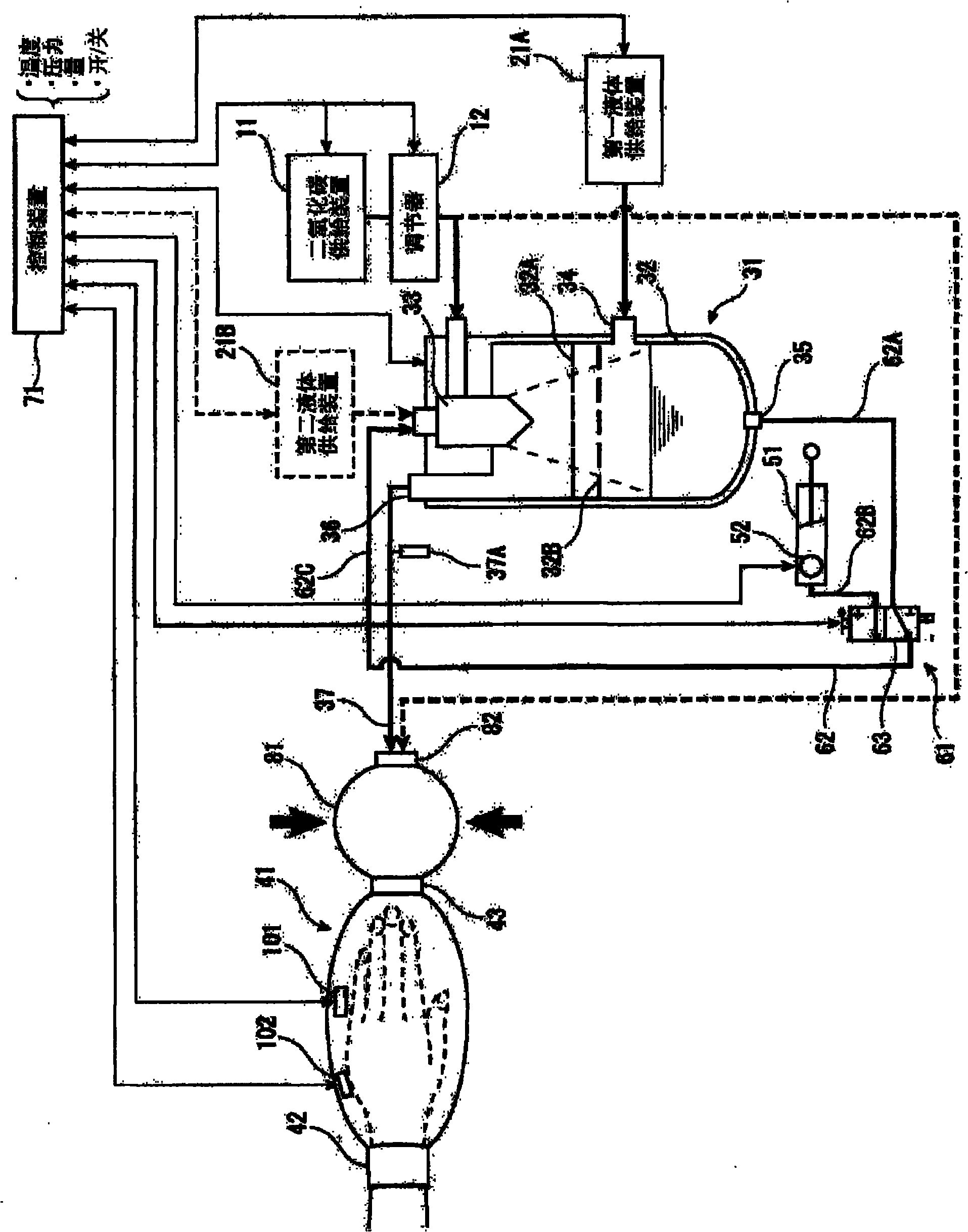
[0036] figure 1 It is an overall schematic view of the carbon dioxide gas mist pressure bath system according to the first embodiment of the present invention. As shown in the figure, the carbon dioxide mist pressure bath system of this embodiment is composed of the following structures: a carbon dioxide supply device 11, a liquid supply device 21, and an aerosol generating device 31 that atomizes and dissolves carbon dioxide and liquid to generate a carbon dioxide mist. , the body pressure bath cover 41 that seals the supplied carbon dioxide gas mist into the inner space, the liquid pressurizer 51 that pressurizes the liquid stored in the carbon dioxide gas mist generating device 31 and supplies the carbon dioxide gas mist generating device 31 again, and is used to make the liquid A liquid circulation device 61 for circulation, a control device 71 for controlling generation and supply of carbon dioxide gas mist, and a pressurizing unit (accumulator) 81 for pressurizing the li...

no. 2 approach

[0062] Figure 6 It is an overall schematic diagram of the carbon dioxide gas mist pressure bath system related to the second embodiment of the present invention. In this embodiment, a carbon dioxide gas mist pressure bath system provided with a device for charging the generated gas mist will be described. where, and figure 1 The parts that are the same as those in the first embodiment shown are assigned the same symbols and detailed explanations are omitted.

[0063] Such as Figure 6 As shown, in the carbon dioxide gas mist pressure bath system of this embodiment, an electrode 92 is provided at the carbon dioxide gas mist outlet 36 of the carbon dioxide gas mist generating device 31 . The electrode 92 is connected to the power supply device 91 , and the control device 71 performs setting of the voltage value and switching control of on and off.

[0064] When the gas mist generated by the carbon dioxide generator is discharged from the carbon dioxide gas mist discharge po...


PUM

PropertyMeasurementUnit
Particle sizeaaaaaaaaaa

Abstract

Provided is a pressurized carbon dioxide mist bathing system whereby a carbon dioxide mist having a high carbon dioxide concentration can be efficiently absorbed through the skin and mucosa of a living body. A pressurized carbon dioxide mist bathing system comprising a carbon dioxide gas-supplying means (11), a liquid-supplying means (21), a carbon dioxide mist-forming means (31) in which the carbon dioxide gas and the liquid are ground and dissolved to give a carbon dioxide mist, a body cover member (41) covering the skin and mucosa of the living body and providing a space in which the carbon dioxide gas mist formed by the carbon dioxide mist-forming means (31) is enclosed , a liquid-circulating means (61) for supplying again the liquid pooled in the carbon dioxide mist-forming means (31) into the carbon dioxide mist-forming means (31), and a body cover member-pressurizing means (81) for pressurizing the inside of the body cover member (41).

Description

technical field [0001] The present invention relates to a carbon dioxide gas mist pressure bath system that efficiently absorbs carbon dioxide from the skin and mucous membranes by bringing the carbon dioxide gas mist into contact with the skin and mucous membranes of a living body at a predetermined pressure or higher. Background technique [0002] In the past, it was known that carbon dioxide (CO 2 ) has the two-sided nature of being easily soluble in water (water-soluble) and oil (fat-soluble), so that it can penetrate into the subcutaneous as long as it contacts the skin and mucous membrane of the body similar to the water-oil mixture, making the penetration The blood vessels in the area dilate to improve blood circulation. Moreover, various physiological effects such as lowering blood pressure, improving metabolism, and promoting excretion of pain substances and wastes are exerted by this blood circulation promoting action. In addition, it also has anti-inflammatory a...

Claims


Application Information

Patent Timeline
IPC IPC(8): A61H33/02A61H33/10A61H35/00
CPCA61H2201/165A61H2205/10A61H33/14A61H2205/065A61H2033/145A61H2205/12A61H2205/06A61H33/02A61H33/10A61H35/00A61H9/00
Inventor 中村正一
Owner 中村正一
Why Eureka
Try Eureka