
Batter separator structures

一种铅酸蓄电池、基层的技术,应用在结构零件、铅酸蓄电池、电池组零部件等方向,能够解决厚度不一致等问题

Inactive Publication Date: 2010-12-15
P H GLATFELTER CO
View PDF4 Cites 8 Cited by
  • Summary
  • Abstract
  • Description
  • Claims
  • Application Information

AI Technical Summary

Problems solved by technology

Absorbent glass mats encounter many of the same problems as additional membranes, ie, the desire to minimize thickness and prevent particle bridging are inconsistent

Method used


Image

  • Batter separator structures
  • Batter separator structures
  • Batter separator structures

Examples


Embodiment Construction

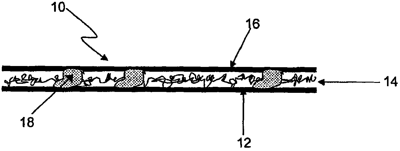
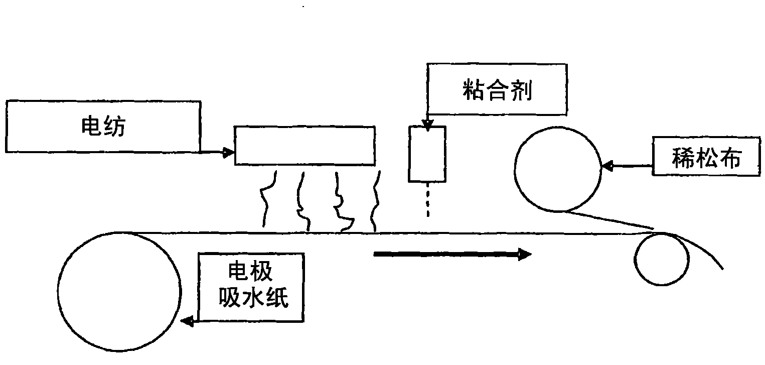
[0028] The invention will now be described with reference to the drawings, wherein like numerals indicate like features. The drawings show certain non-limiting embodiments of the invention. Figure 1a , 1b and 5 are not to scale and are not used for engineering drawings.

[0029] like Figure 1a As schematically shown in , the present invention provides a multilayer composite sheet suitable for use as a battery separator. In certain embodiments, as will now be discussed, the composite sheet can be used as a combined battery electrode blotter / separator. The composite sheet, shown generally at 10, includes a fibrous layer 12 on which is located a non-conductive polymeric nanofiber layer 14 and on layer 14 a polymeric scrim layer 16. In the case of this embodiment, said fibrous layer 12 is electrode absorbent paper. Discrete binder particles 18 bond the nanofibrous layer to both the paper layer and the scrim layer, thereby integrating the three layers to form the composite she...


PUM

PropertyMeasurementUnit
diameteraaaaaaaaaa
diameteraaaaaaaaaa
diameteraaaaaaaaaa

Abstract

A multilayer composite sheet for use in a lead-acid battery includes a) a base layer including paper or a glass fiber mat; b) a layer of polymeric nanofibers bonded with discrete adhesive particles to a first surface of the base layer; and c) a scrim layer bonded with discrete adhesive particles to a surface of the layer of nanofibers opposite the base layer. A plate assembly for a lead-acid battery includes one or more multilayer composite sheets located adjacent or partially enclosing a lead plate.

Description

[0001] Cross References to Related Applications [0002] This application claims priority to US Provisional Patent Application No. 61 / 007082, filed December 11, 2007, which is hereby incorporated by reference in its entirety. Background technique [0003] Lead-acid batteries contain lead plates that can be prepared by applying an aqueous paste of lead oxide (PbO) to a lead grid and then drying the lead grid. In some methods, such as continuous casting methods, the lead oxide is held in place by electrode pasting paper while drying the plate. In other methods, such as the strip casting method, electrode blotters are not required. [0004] Once dry, the lead plates were "formed" by applying an electric charge to the plates while they were immersed in a 6 molar solution of sulfuric acid, resulting in positive and negative plates. Newer production methods involve adding an expander material (powdered sulphate) to the paste to produce the negative plate, so there is no need to fo...

Claims


Application Information

Patent Timeline
Patent Type & Authority Applications(China)
IPC IPC(8): H01M2/16H01M50/417H01M50/423H01M50/437H01M50/451H01M50/457H01M50/491
CPCH01M4/14H01M2/1686H01M2/162H01M2/1626H01M10/06H01M2/1613Y02E60/126H01M2/1673Y10T442/197Y10T442/174Y10T442/155Y10T442/159Y10T442/184Y02E60/10H01M50/44H01M50/4295H01M50/46Y02P70/50H01M50/437H01M50/417H01M50/451H01M50/457H01M50/491H01M50/423H01M50/431H01M50/411H01M50/449B82Y30/00
Inventor W·N··贾斯蒂斯
Owner P H GLATFELTER CO
Learn More