Back distribution type front pneumatic chuck

A technology of pneumatic chucks and chucks, applied in the direction of chucks, etc., can solve the problems of difficult installation of rotary cylinders, inability to realize equipment automation, limited tail space, etc., and achieve the effects of improving productivity, shortening clamping time, and reducing labor intensity.

Inactive Publication Date: 2010-12-22
江苏无锡建华机床附件集团有限公司
View PDF7 Cites 7 Cited by
  • Summary
  • Abstract
  • Description
  • Claims
  • Application Information

AI Technical Summary

Problems solved by technology

Due to the limited space at the rear of some machine tool equipment, it is difficult to install the rotary cylinder. In this case, the ordinary power chuck and rotary cylinder system cannot realize the automation of the above equipment

Method used


Image

  • Back distribution type front pneumatic chuck
  • Back distribution type front pneumatic chuck

Examples


Embodiment Construction

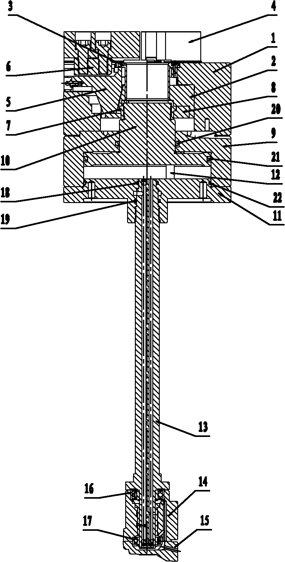
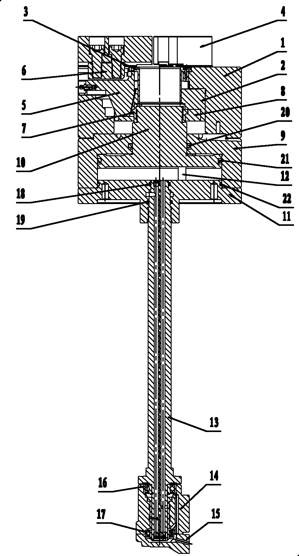
[0010] Below the present invention will be further described in conjunction with the embodiment in the accompanying drawing:

[0011] Such as figure 1 As shown, it includes chuck body 1, wedge sleeve 2, cover 3, three claws 4, three sliding seats 5, three T-blocks 6, push-pull sleeve 7, push-pull ring 8, cylinder body 9, piston 10. Base 11, guide shaft 12, valve stem 13, valve body 14, valve cover 15, bearings 16~17, first sealing ring 18, second sealing ring 19, third sealing ring 20, fourth sealing ring 21, The fifth sealing ring 22 .

[0012] In the present invention, the chuck body 1 and the cover 3 are connected to form the chuck main body, and three straight grooves are provided at the front end of the chuck body 1, and three sliding seats 5 are installed in the three straight grooves, and the three sliding seats 5 pass through the chute and the wedge The heart sleeve 2 is connected, and the three sliding seats 5 are connected with the three claws 4 through the comb te...


PUM


Abstract

The invention relates to a back distribution type front pneumatic chuck which comprises a chuck body, a wedge core sleeve, a retaining cap, three jaws, three sliding bases and three T shaped blocks. The back distribution type front pneumatic chuck is characterized in that an air cylinder body is connected with a base to forma an air cylinder main body, a piston is installed in the air cylinder body and connected with the wedge core sleeve through a push-pull sleeve and a push-pull ring, the wedge core sleeve slides up and down in the chuck body under the driving of the piston, an upper air chamber and a lower air chamber are formed above and below the piston, the base is fixedly connected with an extended valve rod in a thread screwing way, the valve rod and a valve body are connected through a bearing and can rotate relatively at a high speed, and a valve cap is connected with the valve body through a screw. The back distribution type front pneumatic chuck has simple, compact and reasonable structure; since the air cylinder body and the chuck body are connected into a whole and a distributing valve is arranged at the rear part independently, the back distribution type front pneumatic chuck can be successfully installed in a narrow space at the tail part of a machine tool, thereby greatly reducing the labor intensity, shortening clamping time and improving productivity; and in addition, since the clamping force is adjustable, the back distribution type front pneumatic chuck can be matched with numerical control equipment which needs air distribution at the tail part of the machine tool and has limited space at the tail part.

Description

technical field [0001] The invention relates to a post-air distribution type front pneumatic chuck, which is mainly matched with numerical control equipment that requires air distribution at the tail of the machine tool and has limited tail space. It belongs to the technical field of machine tool accessories. Background technique [0002] In the prior art, the power chuck and the rotary cylinder system are relatively similar to the present invention. The usual pneumatic (or hydraulic) chuck is installed at the head of the spindle of the CNC machine tool, and the cylinder (or oil cylinder) is installed at the tail. To loosen the workpiece. Due to the limited space at the rear of some machine tool equipment, it is difficult to install the rotary cylinder. In this case, the ordinary power chuck and rotary cylinder system cannot realize the automation of the above equipment. Contents of the invention [0003] The purpose of the present invention is to overcome the above dis...

Claims


Application Information

Patent Timeline
Patent Type & Authority Applications(China)
IPC IPC(8): B23B31/24B23B31/103
Inventor 王猛韦鸣张震宇宋昱华天虎韩新强许峰唐彦
Owner 江苏无锡建华机床附件集团有限公司
Why Eureka
Try Eureka