Epitaxial wafer tray and support and rotation connecting device matched with same

A technology of rotating connection and rotating driving device, which is applied to chemical instruments and methods, gaseous chemical plating, crystal growth, etc., can solve the problems of prolonging the time required for heating or cooling, increasing the weight of the tray 10, and reducing the mechanical strength, etc., to achieve Effects of heat capacity reduction, material consumption reduction, and weight reduction

Active Publication Date: 2010-12-22
JIANGSU ZHONGSHENG SEMICON EQUIP
View PDF7 Cites 24 Cited by
  • Summary
  • Abstract
  • Description
  • Claims
  • Application Information

AI Technical Summary

Problems solved by technology

[0010] Processing the counterbore 101 on the tray 10 will reduce the thickness of the corresponding part of the tray 10 and reduce the mechanical strength. In order to ensure the mechanical strength of the part of the counterbore 101, the overall thickness of the tray 10 is often increased, thus causing the weight of the tray 10 to increase. , leading to an increase in heat capacity, prolonging the time required for heating or cooling

Method used


Image

  • Epitaxial wafer tray and support and rotation connecting device matched with same
  • Epitaxial wafer tray and support and rotation connecting device matched with same
  • Epitaxial wafer tray and support and rotation connecting device matched with same

Examples


Embodiment 1

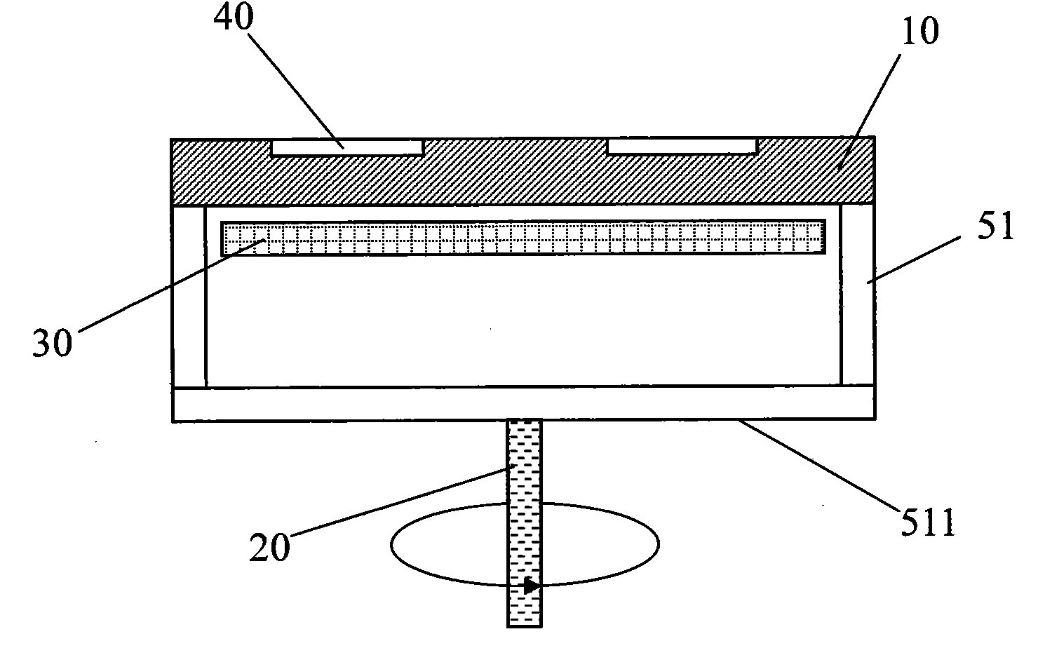
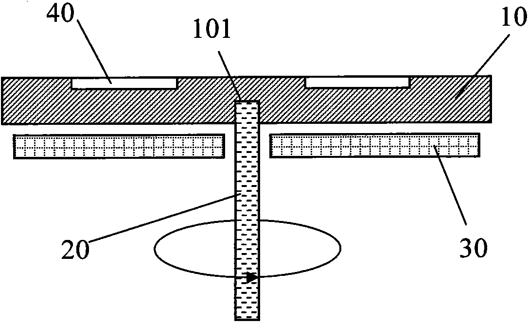
[0056] like Figure 5 or Image 6 As shown, in this embodiment, the tray rotating shaft 100 at the center of the bottom of the tray 10 is in the shape of a ladder protruding downwards, including a cylindrical first boss 110 arranged at the bottom of the tray 10, and arranged on the bottom of the tray 10. Under the first boss 110, the smaller diameter cylinder ( Figure 5 ) or conical ( Image 6 ) of the second boss 120. The annular end surface 111 of the first boss 110 is parallel to the upper surface 11 and the bottom surface 12 of the tray 10 .

[0057] A counterbore 200 is defined at the top of the driving shaft 20 , and an annular top surface 211 of the counterbore 200 is perpendicular to the axis of the driving shaft 20 . When the tray 10 is put into the reaction chamber 50, the second boss 120 of the tray rotating shaft 100 is fully inserted into the counterbore 200, and the side 112 of the second boss 120 is used as the guide in the vertical direction of the tray 10...

Embodiment 2

[0060] like Figure 7 As shown, in this embodiment, the tray shaft 100 at the center of the bottom of the tray 10 is a cylindrical or conical step (not shown in the figure) protruding downwards, and the end surface 121 of the step is in contact with the tray 10. The upper surface 11 and the bottom surface 12 are all parallel.

[0061] The tray rotating shaft 100 is positioned on the plane through its step side 122, so that when it is inserted into the counterbore 200 opened at the top of the drive shaft 20, the step end surface 121 falls on the bottom surface 222 of the counterbore 200, and the tray 10 is positioned vertically in the reaction chamber. 50 miles, and the tray 10 is supported by the drive shaft 20 . The effective area of ​​the tray 10 supported by the bottom surface 222 of the counterbore 200 of the drive shaft 20 is determined by the diameter of the tray shaft 100 .

[0062] When the tray rotating shaft 100 is inserted into the counterbore 200, the step end su...

Embodiment 3

[0064] It is different from the above-mentioned embodiment 1 and 2 in that the tray 10 and the drive shaft 20 are driven to rotate together through the cooperation of a pair of contact surfaces on the tray shaft 100 and the drive shaft 20 parallel to the upper surface 11 and the bottom surface 12 of the tray 10 .

[0065] like Figure 8 As shown, in this embodiment, the tray rotating shaft 100 is provided downward with a step protruding from the bottom surface 12 of the tray 10, which may be cylindrical or conical, and correspondingly the counterbore 200 at the top of the drive shaft 20 is also set to be cylindrical or conical. Conical or other shapes that match the tray shaft 100, after the tray shaft 100 is inserted into the counterbore 200, the step side 131 of the tray shaft 100 contacts the side 231 of the counterbore 200 of the drive shaft 20, supports the tray 10, and serves as The contact surfaces of the tray rotating shaft 100 and the drive shaft 20 are frictionally d...


PUM


Abstract

The invention relates to an epitaxial wafer tray for an MOCVD (Metal Organic Chemical Vapor Deposition) reaction cavity and a support and rotation connecting device matched with same. When the tray is mechanically loaded and unloaded, and a rotating shaft projecting outward from the center of the bottom of the tray is inserted into a counter bore on the top of a drive shaft perpendicular to the rotating shaft. Respectively arranged contact surfaces parallel to the surface of the tray or contact surfaces on the corresponding side face are used for supporting the tray, and the friction transmission between the contact surfaces is used for driving the tray to rotate when the drive shaft rotates. The friction transmission is changed into contact transmission by arranging an axial locating slot and a locating key, the rotation of the tray is ensured to be consistent with that of the drive shaft, and the security of the tray under middle-high speed long-term rotation is improved. The projecting tray rotating shaft is easy to process the surfaces contacted by friction, the entire thickness of the tray is not increased under the condition of ensuring the mechanical strength of the corresponding part on the tray, and the heat capacity of the tray is reduced. Thus, the time required by heating and cooling the tray is shortened, and the production efficiency is improved, which is beneficial to quick temperature adjustment and control required by epitaxial reactions.

Description

technical field [0001] The invention relates to an epitaxial wafer tray which is picked and placed by a manipulator in a MOCVD (metal organic chemical vapor deposition) system for producing compound semiconductor optoelectronic devices, and a coupling device cooperating with it to support from the center and drive the tray to rotate. Background technique [0002] Metal organic chemical vapor deposition system (hereinafter referred to as MOCVD system) is a kind of equipment used for epitaxial growth of semiconductor thin film to form semiconductor devices such as LED (light emitting diode). [0003] In large-scale production, the batch processing method is usually used to increase the system output, that is, a batch of epitaxial wafers 40 (or called epitaxial chips, substrate chips, etc.) Replace with a new batch of epitaxial wafers 40, and start the next round of reaction treatment. Several epitaxial wafers 40 are placed on the same substrate tray 10 ( figure 1 ), the auto...

Claims


Application Information

Patent Timeline
Patent Type & Authority Applications(China)
IPC IPC(8): C30B25/12
CPCC30B25/12H01L21/68771H01L21/68764H01L21/68792H01L21/67754C23C16/4584C23C16/4585
Inventor 金小亮陈爱华孙仁君张伟
Owner JIANGSU ZHONGSHENG SEMICON EQUIP
Why Eureka
Try Eureka