
Building roof with air space

A technology of air interlayer and barrier film, applied in the direction of roof, building, building structure, etc., to achieve the effect of improving thermal performance

Inactive Publication Date: 2012-05-23
SHENZHEN UNIV
View PDF0 Cites 0 Cited by
  • Summary
  • Abstract
  • Description
  • Claims
  • Application Information

AI Technical Summary

Problems solved by technology

[0004] Therefore, the existing technology still needs to be improved and developed

Method used


Image

  • Building roof with air space
  • Building roof with air space
  • Building roof with air space

Examples


Embodiment Construction

[0026] The specific implementation modes and examples of the present invention will be described in detail below in conjunction with the accompanying drawings.

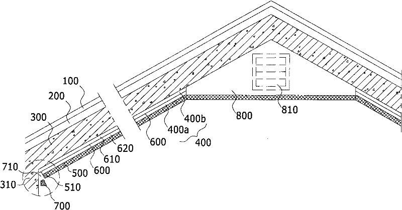
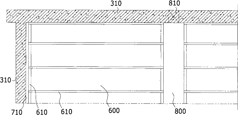
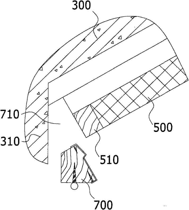
[0027] A building roof with an air interlayer of the present invention, one of its specific implementations, as attached figure 1 As shown, it includes a roof body 300 on the top of the building, which is used to connect with the wall body 310 of the building to form an indoor space; usually the indoor space is located on the top floor of the building; the roof body 300 can be The roof of the attic on the top floor of a single-family villa building can also be the roof of the top floor unit of an ordinary residential building. Specifically, it can be made of reinforced concrete structural panels, and glass fiber asphalt tiles 100 and cement tiles can also be arranged outside the reinforced concrete structural panels. Polyphenylene particle insulation layer 200; An air interlayer 400 is arranged on the inside of the r...


PUM


Abstract

The invention discloses a building roof with an air space in which a thermal radiation barrier film is hung in the middle. The building roof comprises a roof body arranged at the top pf a building and connected to walls of the building so as to form an indoor space. The air pace is arranged on an inner surface of the roof body. The thermal radiation barrier film is hung in the middle of the air space and divides the air space into an outer air space and an inner air space. Under a sealing working condition, the air space is used for heat insulation of the indoor space, and under a ventilation working condition, the air space is used for heat insulation of the indoor space. As the air space capable of working under the sealing or ventilation working condition is reserved on the inner surface of the roof body, the two different thermotechnical requirements of winter and summer are relatively better taken into account for the building roof; particularly, the thermal radiation barrier film arranged in the air space further improves the thermotechnical performance of the building roof; and the building roof is very suitable for the energy-saving and emission-reduction upgrading alteration of the building and of great significance in new building works and the green alteration of the conventional buildings.

Description

technical field [0001] The invention relates to the field of building roofs used to connect walls of buildings to form indoor spaces, and more specifically, the improvement relates to a building roof in which suspended thermal radiation blocking films divide air interlayers. Background technique [0002] The roof of a building occupies a large proportion of the space facing the sun, and its thermal performance has a greater impact on the comfort of the living interior space; The technical method is to reduce the heat transfer coefficient of the building roof itself and improve its thermal inertia index, including using materials with low thermal conductivity and increasing the thickness of the insulation layer. [0003] However, in the prior art, the technical means of using materials with low heat transfer coefficient and increasing the thickness are simple, and there are still certain limitations in terms of technical effect and economy, and it is impossible to take into ...

Claims


Application Information

Patent Timeline
Patent Type & Authority Patents(China)
IPC IPC(8): E04D11/00E04D13/16E04D13/17
CPCY02B80/32Y02A30/254
Inventor 袁磊张道真
Owner SHENZHEN UNIV
Learn More