

Porous filter cartridge
A filter cartridge and filter technology, which can be used in ultrafiltration, sampling devices, instruments, etc., can solve the problems of liquid residue, pollution, difficult measurement, etc., and achieve the effect of effective filtration and extraction and economic advantages.
- Summary
- Abstract
- Description
- Claims
- Application Information
AI Technical Summary
Problems solved by technology
Method used
Image

Examples
no. 1 approach
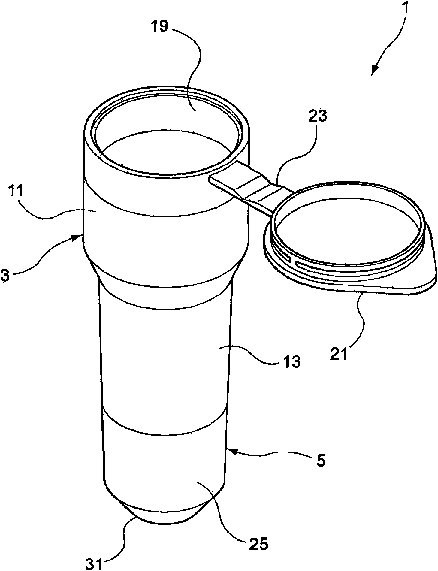
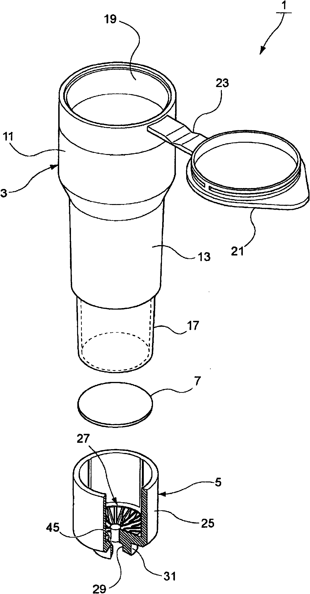
[0068] figure 1 is a perspective view of a porous filter cartridge of the present invention, figure 2 yes figure 1 An exploded view of a porous filter cartridge.
[0069] Such as figure 1 and 2 As shown, the porous filter cartridge of the first embodiment mainly includes a cylinder portion 3 , a cover 5 and a porous filter sheet 7 .
[0070] The barrel portion 3 is made of an insert-injection moldable resin material such as polypropylene, polystyrene, polycarbonate, or polyvinyl chloride. The barrel 3 has an inlet 19 at its cylindrical upper part and a cover 21 connected to the inlet 19 by a hinge 23 . The barrel portion 3 is composed of a large diameter portion 11 , a small diameter portion 13 , and a fusion portion 17 fused to the cap 5 located below the small diameter portion 13 .
[0071] The cover 5 is a cylinder with a bottom, and similar to the barrel 3 , the cover 5 is also made of resin material that can be insert-molded such as polypropylene, polystyrene, poly...
no. 2 approach
[0090] A second embodiment of the porous cartridge of the present invention is described below.
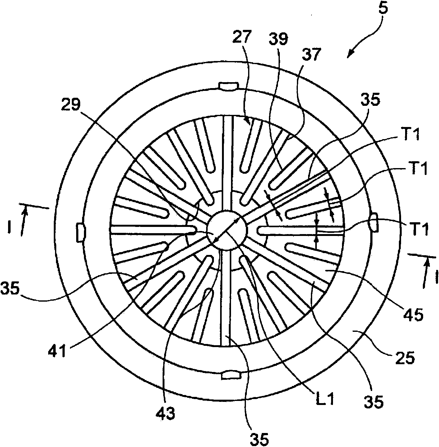
[0091] The porous filter cartridge of the second embodiment is identical in structure to the first embodiment except that the shapes of the intersecting ribs 35 and the auxiliary ribs 37 and 39 are different.
[0092] Figure 8 is a partially cutaway perspective view of a cover for the second embodiment (equivalent to Figure 5 ). Figure 9 is a cross-sectional view of the cover taken along the line I-I (equivalent to Figure 4 ).
[0093] Such as Figure 8As shown, in the cover of the second embodiment, the cross-shaped rib 35, the auxiliary ribs 37 and 39 are formed so that they have a series of protrusions 49 bulged toward the porous filter side on the top surface. The height of each protrusion 49 is smaller than the thickness of the tops of the cross-shaped rib 35 and the auxiliary ribs 37 and 39 . Each protrusion has a smooth curve. Although in the example shown each r...
Embodiment 1
[0166] The effect of the porous filter cartridge of the present invention was tested. The results obtained are described below. Burst resistance test
[0167] Example 1 is a porous filter cartridge with 6 intersecting ribs. The connecting portion of the cross-shaped rib has a convex surface. The diameter of the outlet opening of the cap is 2 mm. Comparative Example 1 is a porous filter cartridge different from Example 1 in that the connecting portion of the rib has a flat top surface. Comparative Example 2 is a porous filter cartridge different from Example 1 in that cross-shaped ribs are not formed. These filter cartridges were placed in a centrifuge (MX-300, available from Tomy Seiko Co., Ltd.), and rotated with gradually increasing rotation speed (8000 rpm and 15000 rpm), and the rupture of the porous filter discs in these filter cartridges was detected. The results are shown in Table 1 below. The results shown are the number of times no rupture occurred out of 10 tes...
PUM
| Property | Measurement | Unit |
|---|---|---|
| pore size | aaaaa | aaaaa |
| loss value | aaaaa | aaaaa |
| thickness | aaaaa | aaaaa |
Abstract
Description
Claims
Application Information