Esophageal stent forceps

A technology of esophagus and arc-shaped hook, applied in stents, medical science, prosthesis, etc., can solve the problems of esophageal stent removal, canceration, and additional pain for patients, and achieve the effect of facilitating capture and enhancing firmness

Inactive Publication Date: 2010-12-29
尹秋伟
View PDF6 Cites 8 Cited by
  • Summary
  • Abstract
  • Description
  • Claims
  • Application Information

AI Technical Summary

Problems solved by technology

Since the hook has a rigid structure and is hooked in one direction (the opening direction of the hook), when using the hook to capture the looped thread at the upper end of the esophageal stent through the endoscope, it often takes many repeated attempts, and the operation is time-consuming and laborious, causing the esophageal stent Very difficult to remove

Method used


Image

  • Esophageal stent forceps
  • Esophageal stent forceps
  • Esophageal stent forceps

Examples


Embodiment 1

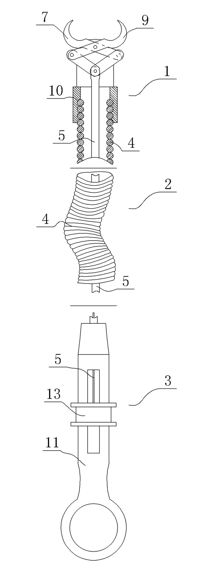
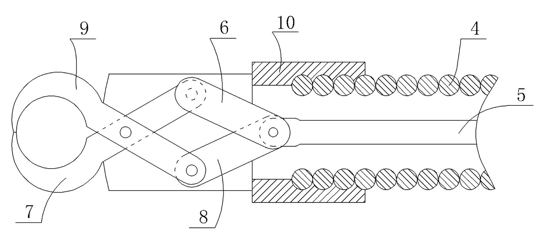
[0024] Example 1 , figure 1 A schematic structural view of Example 1 is given. The esophageal stent removal forceps of the present invention include a forceps head 1, a middle portion 2 and an operating portion 3; image 3 and Figure 4 A schematic diagram of the mechanism of the pliers head in Example 1 is given, Figure 9A schematic diagram of the structure of the operating unit 3 is given. The shown pliers head 1 includes a fixed seat 10, a first movable rod 6, a second movable rod 8, a first arc-shaped hook 7, and a second arc-shaped hook 9; the middle part 2 includes a flexible shell 4 and a flexible soft Line 5 ; the operating part includes a cylinder 20 , a ring 12 and a moving slider 13 . The inside of the flexible housing 4 is a hollow body, and the flexible housing 4 can be bent; the flexible cord 5 is arranged in the inner cavity of the flexible housing 4, the flexible cord 5 and the flexible housing 4 are not fixed, and the flexible The cord 5 can move under ...

Embodiment 2

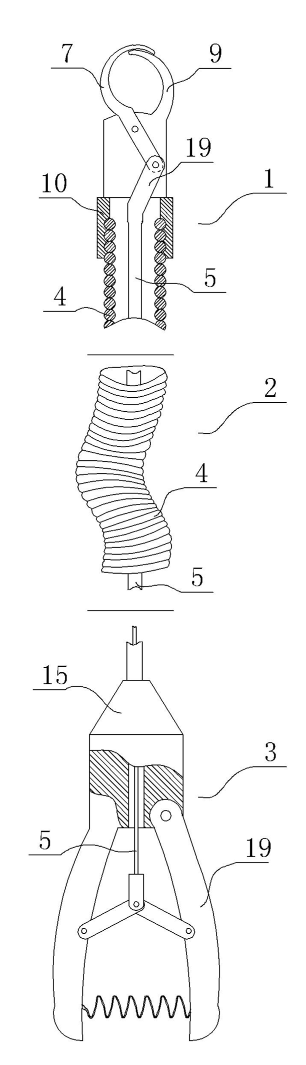
[0028] Example 2 , figure 2 A schematic diagram of the structure of the second embodiment of the present invention is given, except that the structure of the middle part 2 is the same as that of the first embodiment, and the pliers part 1 and the operation part 3 are different from those of the first embodiment. Figure 7 and Figure 8 A schematic diagram of the specific structure of the pliers head 1 in this embodiment is given, the fixed seat 10 shown is fixedly connected to the flexible shell 4, the second arc-shaped hook 9 is fixed to the fixed seat 10, and the first arc-shaped hook 7 passes through The rotating shaft is fixed on the fixed seat 10. The end of the flexible cord 5 is provided with a bending portion 19 forming a certain angle with the flexible cord. The angle formed by the bending portion 19 and the flexible cord 5 is an obtuse angle. The ends of the rods 6 are pivotally connected together. In this way, during the reciprocating movement of the flexible ...


PUM


Abstract

The invention relates to a pair of esophageal stent forceps, which comprises a forceps head part, a middle part and an operating part, wherein the middle part comprises a flexible shell and a flexible wire; the inner part of the flexible shell is a cavity; the flexible wire is arranged in the inner cavity of the flexible shell; the forceps head part comprises a first arc hook, a second arc hook and a fixed seat; the second arc hook is matched with the first arc hook; the fixed seat is fixedly connected with the flexible shell; at least one of the first arc hook and the second arc hook is connected with the flexible wire; the arc hook connected with the flexible wire is rotatablely fixed on the fixed seat; the operating part comprises a base and a moving mechanism; the base is fixedly connected with the flexible shell; the moving mechanism can move on the base; and the moving mechanism is fixed with the flexible wire. The invention changes the original open hook structure, can conveniently take out the esophageal stent, and can conveniently control the opening and closing of the first arc hook and the second arc hook.

Description

technical field [0001] The invention relates to an esophageal stent (cylindrical structure, commonly used as a "Z"-shaped stent or a mesh-shaped memory alloy stent, hereinafter referred to as an esophageal stent) removal forceps, and more specifically relates to a forceps used in conjunction with an endoscope. The esophageal stent removal forceps that can effectively remove the esophageal stent. Background technique [0002] During the treatment of patients with esophageal stenosis (benign stenosis or malignant stenosis), in order to relieve esophageal obstruction and improve or restore the patient's oral feeding function, it is often necessary to place an esophageal stent in the patient's esophagus to restore patency. When placing an esophageal stent, it is often necessary to adjust or take it out and replace it due to calculation errors or improper operation; The stent slipped toward the stomach; benign esophageal strictures also needed to be removed after treatment. The...

Claims


Application Information

Patent Timeline
IPC IPC(8): A61F2/84A61F2/95
Inventor 尹秋伟
Owner 尹秋伟
Why Eureka
Try Eureka