
Pulse turbulence flow field fluidized mineral separator

A technology of mineral separation and turbulent flow field, applied in the direction of solid separation, wet separation, chemical instruments and methods, etc., can solve the problems of difficult coal separation, high content of fine coal, low ash content of coarse coal slime, etc., and achieve flexible Adjustable and controllable sorting density to ensure full dispersion effect

Inactive Publication Date: 2010-12-29
WEIHAI HAIWANG HYDROCYCLONE
View PDF10 Cites 12 Cited by
  • Summary
  • Abstract
  • Description
  • Claims
  • Application Information

AI Technical Summary

Problems solved by technology

[0002] my country's coal quality is characterized by a large content of fine-grained coal. In addition, the ash content of my country's coarse coal slime is relatively low. To produce qualified clean coal, the separation density must be reduced very low. Most coal slimes become difficult or extremely difficult to separate. At present, the separation equipment used in the domestic industry for the separation of coarse coal slime is not ideal, and most of them are in a deactivated state. Therefore, research and promotion of coarse coal with high separation efficiency at low separation density Slime separation equipment has important practical significance, which is also one of the important ways to reduce the sulfur content of the total coal clean coal in my country and reduce coal pollution

Method used


Image

  • Pulse turbulence flow field fluidized mineral separator
  • Pulse turbulence flow field fluidized mineral separator
  • Pulse turbulence flow field fluidized mineral separator

Examples


Embodiment Construction

[0012] The present invention will be further described below in conjunction with accompanying drawing:

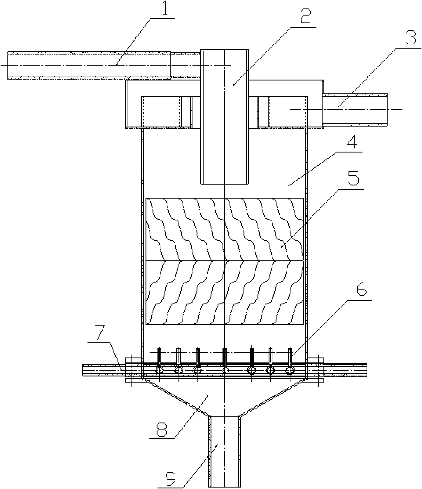
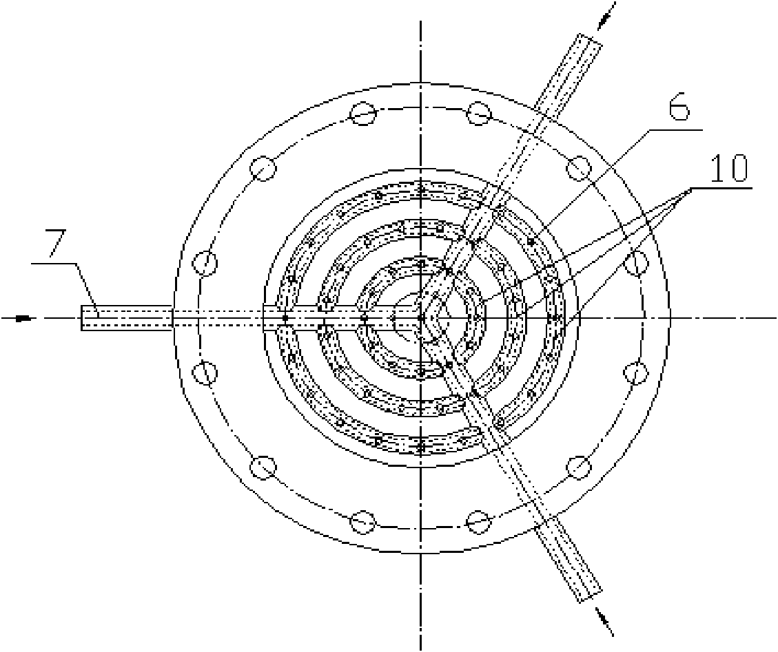
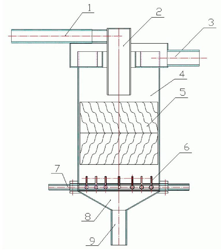
[0013] As shown in the accompanying drawings, a pulse turbulent field fluidized mineral separator is provided with a cylindrical body 4. The cross section of the body 4 is circular, square or other shapes, and its diameter can be from It varies from 1800mm to 3600mm. The height of the body 4 is generally 1.0-1.5 times the diameter. The upper end of the body 4 is provided with a feed well 2 and an overflow pipe 3. The feed well 2 is provided with a feed pipe 1. The pipe 1 is connected with the upper part of the feed well 2 in the form of involute or spiral, and the outlet of the feed well 2 is located at 3 / 4 of the height of the machine body 4, so that the incoming ore slurry is uniform across the entire feed cross-section The ground distribution is conducive to the stability of the flow field at the feeding place. On the other hand, it can also realize the preliminary separ...


PUM


Abstract

The invention relates to mineral separation machinery, in particular to a high-separation precision pulse turbulence flow field fluidized mineral separator. The mineral separator is characterized in that: the separator is provided with a cylindrical machine body; a feed well and an overflow pipe are arranged at the upper end of the machine body; a feed pipe is arranged on the feed well; a discharge cone is arranged at the lower end of the machine body; a discharge port is formed on the discharge cone; and a fluid distributor and a separator which consists of separating plates are arranged inside the machine body. The invention is novel separation technology with the advantages of high efficiency and high treatment capacity of self-production medium and low operating cost, combines the fluidization technology, the pulse turbulence flow field hindered falling technology and the irregular inclined corrugated plate separation technology, uses coarse particle high-density materials in the feed materials as a self-medium solid, makes the separating bed fluidized by using hydraulic jump upward flow, improves the separating medium density, makes materials with density higher than that of the separating medium pass through the bed to be settled at the bottom, makes materials with density lower than that of the separating medium float upward to enter overflow, and has the advantages of unique structural design, high adaptability to feed concentration and material properties, and capacities of controlling the cleaned coal ash no more than 15 percent through separation at one time and controlling 42 to 80 percent tailings coal ash to follow material property.

Description

Technical field: [0001] The invention relates to a mineral sorting machine, in particular to a pulse turbulent field fluidized mineral sorting machine with high sorting precision. Background technique: [0002] my country's coal quality is characterized by a large content of fine-grained coal. In addition, the ash content of my country's coarse coal slime is relatively low. To produce qualified clean coal, the separation density must be reduced very low. Most coal slimes become difficult or extremely difficult to separate. At present, the separation equipment used in the domestic industry for the separation of coarse coal slime is not ideal, and most of them are in a deactivated state. Therefore, research and promotion of coarse coal with high separation efficiency at low separation density Slime separation equipment has important practical significance, which is also one of the important ways to reduce the sulfur content of the total clean coal of our country and reduce the p...

Claims


Application Information

Patent Timeline
Patent Type & Authority Applications(China)
IPC IPC(8): B03B7/00
Inventor 刘培坤王霄鹏西作海崔学奇葛家君
Owner WEIHAI HAIWANG HYDROCYCLONE
Learn More