Rotating and swinging joint module of robot of single degree of freedom

A technology of joint modules and robots, which is applied in the field of robots, can solve the problems of unsatisfactory weight-moment ratio, difficulty in meeting a wide range of needs, and many degrees of freedom of modules, and achieve the effect of compact structure, small axial size, and good reliability

Inactive Publication Date: 2010-12-29
SOUTH CHINA UNIV OF TECH
View PDF10 Cites 33 Cited by
  • Summary
  • Abstract
  • Description
  • Claims
  • Application Information

AI Technical Summary

Problems solved by technology

In China, Harbin Institute of Technology has developed a modular joint (patent number: ZL1807032.A), and South China University of Technology has also developed the first generation of robot swing joint modules (patent number: ZL200820202740.3), but its structure Complicated, less than ideal weight-to-moment ratio
In short, although many joint modules have been developed, they are either of a single type (such as Amtec's PowerCube), or the price is extremely high (such as the Robotics Research module), or the module has more degrees of freedom (such as TODOM has two degree of freedom, which can only constitute a robot with even degrees of freedom), or the module itself is simple and targeted (such as various micro-joint modules for reconfigurable robots or snake robots), and it is difficult to meet the requirements of building any robot of conventional size wide range of needs

Method used


Image

  • Rotating and swinging joint module of robot of single degree of freedom
  • Rotating and swinging joint module of robot of single degree of freedom
  • Rotating and swinging joint module of robot of single degree of freedom

Examples


Embodiment Construction

[0016] In order to better understand the present invention, the following will be further described in conjunction with the accompanying drawings.

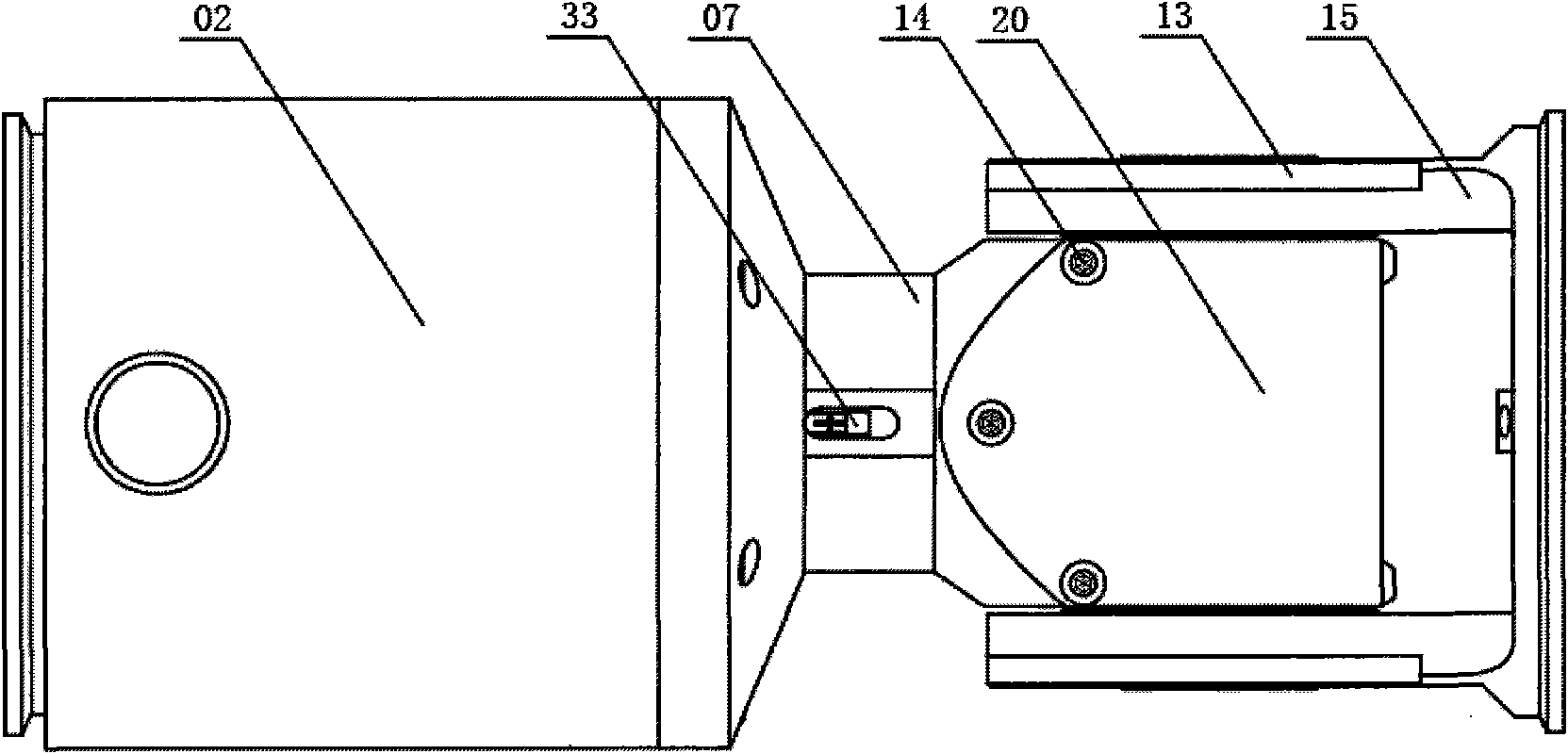
[0017] like figure 1 Shown is the appearance diagram of the swing joint module of the present invention. The motor base 02 and the joint base 07 in the figure are fixed together by screws as the basic part of the entire joint module, and the joint swing member 15 and the transition end cover 13 of the swing joint are also fixed together by screws. These two parts can make relative swing. Cover 20 is fixed on the joint seat 07 with screw 14, and a pair of bevel gears and their shafts are wrapped, which is both for safety and for sealing and dustproof.

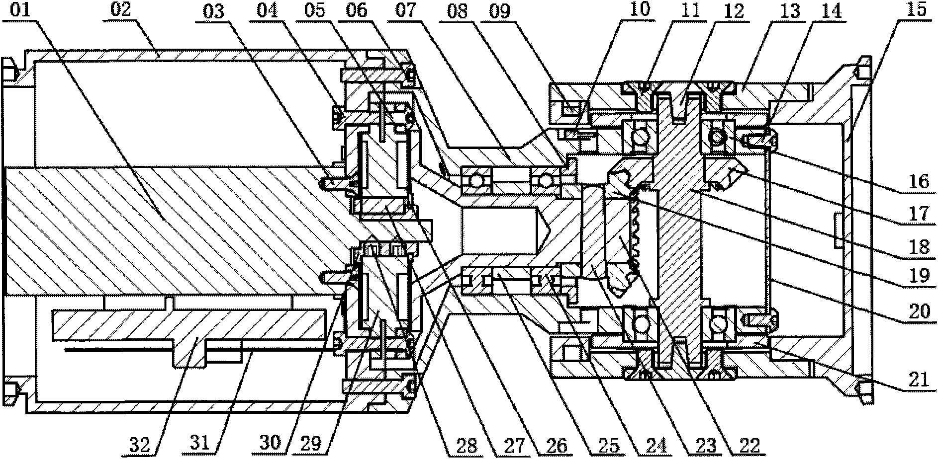
[0018] like figure 2 Shown is a cross-sectional view of the T-shaped joint module of the present invention. exist figure 2 In , the joint axis of the module is perpendicular to the centerline of the connecting rod. Parts include: servo motor and photoelectric encoder assembl...


PUM


Abstract

The invention relates to a rotating and swinging joint module of a robot of single degree of freedom. The joint module is provided with a rotation degree of freedom, and the joint spindle thereof is vertical to the connection axis of the module to form swinging movement. The joint module is matched with a corresponding control system to realize movement or moment control, and joint parts and limiting position are detected by a Hall switch. The rotating and swinging joint module mainly comprises a servo motor and a photoelectric encoder assembly, a disk-type harmonic wave reducer assembly, a harmonic wave reducer output shaft, a motor base, a joint base, a bearing, a shaft cover, an end cover, a pair of bevel gears, a joint spindle and the like, wherein a motor shaft is connected with the wave generator of the harmonic wave reducer through the shaft sleeve, and the output rigid wheel of the harmonic wave reducer is fixedly connected with an output disk; a pair of bevel gears is arranged between the output disk and the joint spindle; the joint spindle is connected with a joint oscillating piece by a trapezoidal key to finally realize movement and power transmission. The module has compact structure and is convenient to connect with other modules or parts and can be combined and built into various robots or other electromechanical systems.

Description

technical field [0001] The invention relates to the technical field of robots, in particular to a single-degree-of-freedom robot joint module. Background technique [0002] Robot technology has made great progress so far, but there is still a considerable distance from a large number and general application in social production and human life. The reason is that important factors include the function, performance and intelligence of the robot itself, as well as the complexity and high cost of the system. Although robots have great flexibility and elasticity for certain applications, most of the existing robot systems often have only one main function and fixed configuration for specific purposes and occasions, lacking functional expansion and reconfiguration. structural. Synthesizing and integrating multiple functions in one body is an important trend in the development of robotic systems at present and in the future. In addition, it costs a lot to develop a specific robo...

Claims


Application Information

Patent Timeline
Patent Type & Authority Applications(China)
IPC IPC(8): B25J17/00B25J13/00
Inventor 朱海飞李湛初管贻生张宪民
Owner SOUTH CHINA UNIV OF TECH
Why Eureka
Try Eureka