Two-degree-of-freedom robot wrist

A robot and degree-of-freedom technology, applied in the field of robot wrists, can solve the problems of complex structure, large overall weight, and difficult control of robot wrists, and achieve the effects of simple structure, light overall weight, and high integration.

Inactive Publication Date: 2010-12-29
HARBIN INST OF TECH
View PDF6 Cites 46 Cited by
  • Summary
  • Abstract
  • Description
  • Claims
  • Application Information

AI Technical Summary

Problems solved by technology

[0003] The purpose of the present invention is to provide a robot wrist with two degrees of freedom to solve the problems of complex structure, large overall weight, difficult control and low integration in existing robot wrists

Method used


Image

  • Two-degree-of-freedom robot wrist
  • Two-degree-of-freedom robot wrist
  • Two-degree-of-freedom robot wrist

Examples


specific Embodiment approach 1

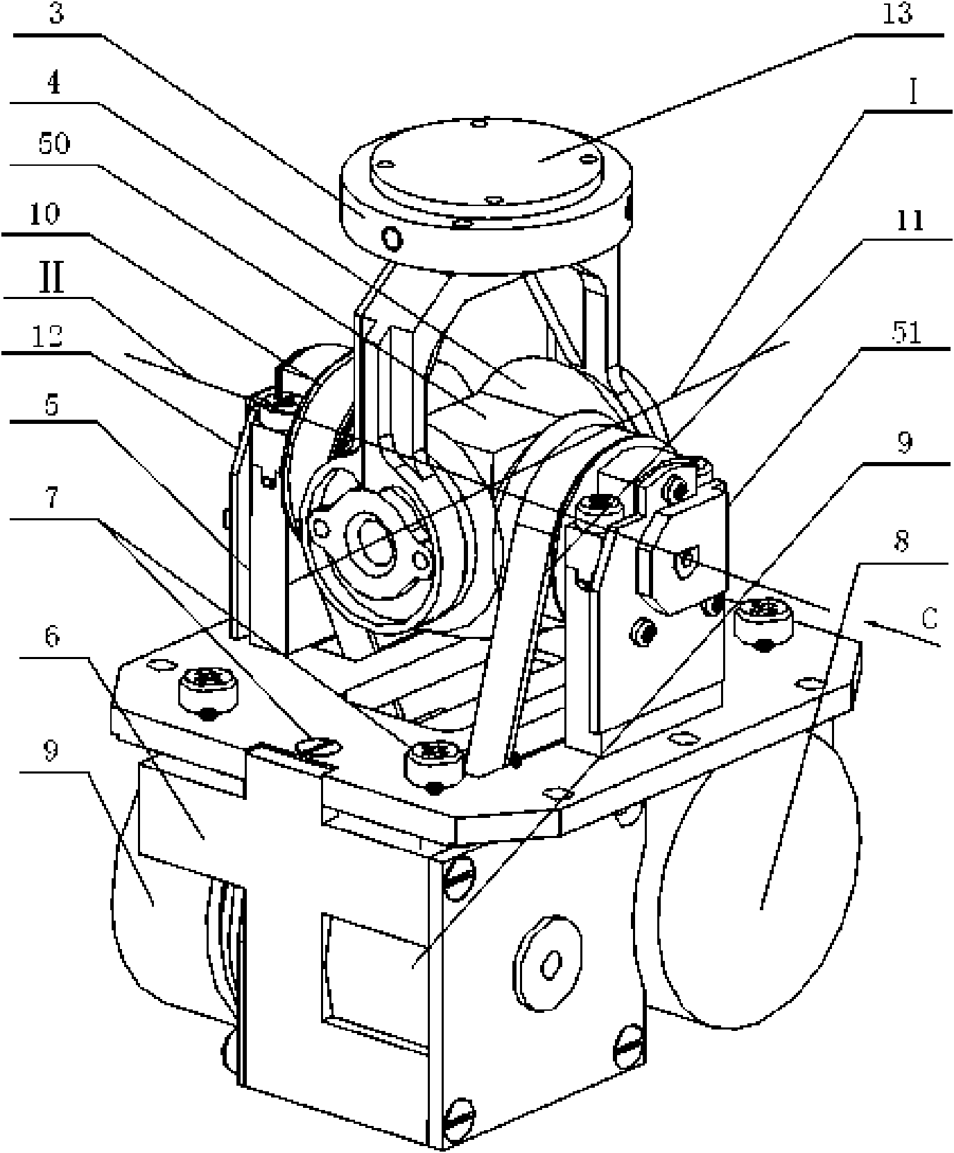
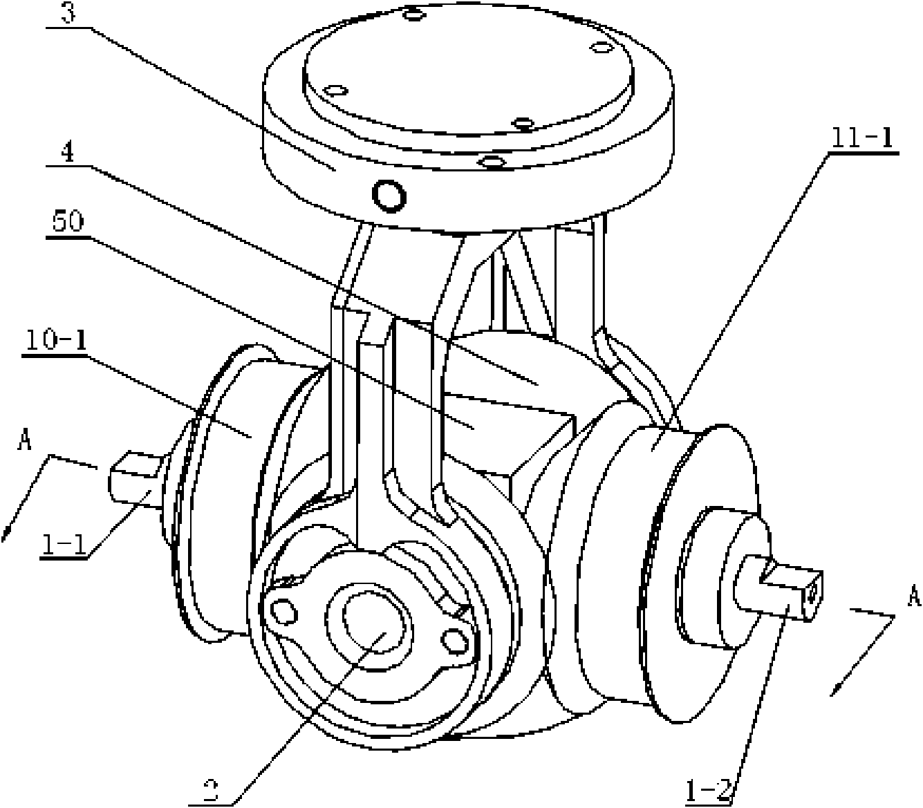
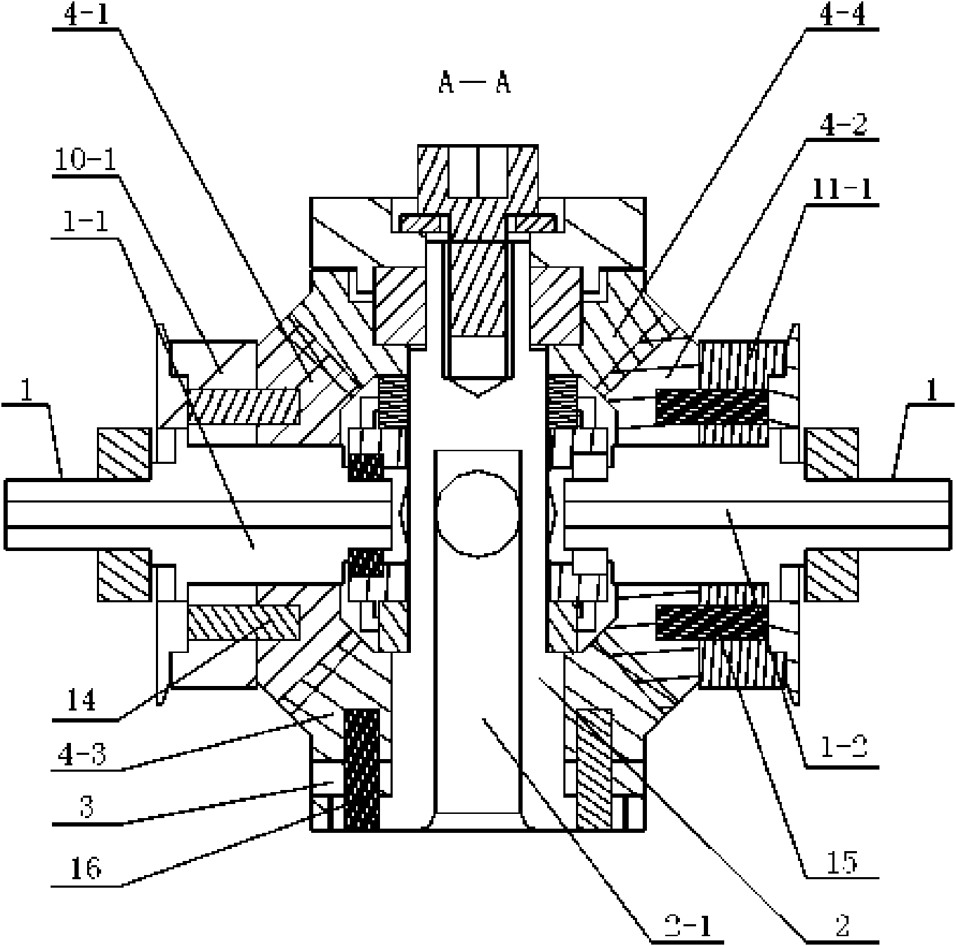
[0007] Specific implementation mode one: combine Figure 1-Figure 19 Describe this embodiment, the robot wrist of this embodiment is composed of torque sensor 3, differential mechanism 4, support frame 5, support block 50, driving frame 6, pretensioning mechanism 7, first driver 8, second driver 9, first Toothed belt transmission mechanism 10, the second toothed belt transmission mechanism 11, the first position sensor 12, the second position sensor 51, the end circuit board 13, the electrical wiring 25 and the wrist electrical equipment 52 constitute; The central axis I of the driving shaft 2 and the central axis II of the driving shaft 1 are arranged in the same horizontal plane and vertically intersect each other. The driving shaft 1 of the differential mechanism is composed of the first driving half shaft 1-1 and the second driving half shaft 1-2 Among the two input bases 3-1 of the torque sensor 3, the one adjacent to the first driven bevel gear 4-3 of the differential me...

specific Embodiment approach 2

[0010] Specific implementation mode two: combination figure 1 and Figure 10 Describe this embodiment, the support frame 5 of this embodiment is made up of support bottom plate 5-1 and two support arms 5-2; The two support arms 5-2 are respectively the first support arm 5-2-1 and the second support arm 5-2-2, and four pre-tightening threaded holes are arranged on the support bottom plate 5-1, and four pre-tightening threaded holes Corresponding to the four top corners of the bracket base plate 5-1, a keyway 5-3 is respectively arranged on the two opposite sides of the bracket base plate 5-1, and two key grooves 5-3 are arranged oppositely. The bracket base plate 5 There are two screw vias on -1. With such arrangement, the structure is simple and the installation of the differential mechanism 4 is easy. Others are the same as in the first embodiment.

specific Embodiment approach 3

[0011] Specific implementation mode three: combination figure 1 , Figure 16 and Figure 17 Describe this embodiment, the torque sensor 3 of this embodiment is made up of cross-shaped strain beam 3-2, four strain gauges 3-3, input base 3-1 and output base 3-4; Output base 3-4 A cross-shaped strain beam 3-2 is fixed between the input base 3-1, there are two input bases 3-1, and the two input bases 3-1 are arranged oppositely, the cross-shaped strain beam 3-2 A strain gauge 3-3 is bonded on the upper surface of each strain beam. The torque sensor 3 detects the force and strain of the cross-shaped strain beam 3-2, and the opposite pair of strain beams respectively detects the strain in the pitch and roll directions; the output base 3-4 of the torque sensor 3 is connected to the wrist end effector , the end circuit board 13 is affixed to the output base 3-4 of the torque sensor 3, and it has no force contact with the cross-shaped strain beam 3-2 of the torque sensor 3, and the ...


PUM


Abstract

The invention discloses a two-degree-of-freedom robot wrist, which relates to a robot wrist and aims to solve the problems of complex structure, heavy weight, high control difficulty and low integration level existing in the conventional robot wrist. One of two input bases of a torque sensor is connected with a first driven bevel gear of a differential mechanism while the other is sleeved on a driven shaft of the differential mechanism; a support block is arranged on a bracket bottom plate of a support bracket; the differential mechanism is supported by the support block and two support arms of the support bracket; a driving frame is connected with the support bracket through a pre-tightening mechanism; first and second drivers are fixed on the driving frame and have opposite transmission directions; the first and second drivers are in transmission connection with first and second driving half shafts of the differential mechanism through first and second toothed belt transmission mechanisms; first and second position sensors are arranged on the first driving half shaft of the differential mechanism; and a tail end circuit board is fixedly arranged on an output base of the torque sensor. The robot wrist has the advantages of simple structure, light overall weight, easy control, high integration level and wrist pitching and deflection degrees of freedom.

Description

technical field [0001] The invention relates to a robot wrist. Background technique [0002] Robot wrist is an important part of robot technology. After years of development and practice, various wrist mechanisms have been produced one after another. These mechanisms mostly use two sets of independent and similar structures to realize the pitch and yaw rotation of the wrist, which will lead to complex structure of the wrist and large overall weight, and the weight of the mechanism of the latter degree of freedom becomes the load of the mechanism of the former degree of freedom, and It is easy to cause the rotation axes of the wrist part to disjoint or produce offset distances, which brings difficulties to the control of the robot wrist, and the integration level is low. Contents of the invention [0003] The object of the present invention is to provide a robot wrist with two degrees of freedom to solve the problems of complex structure, large overall weight, difficult co...

Claims


Application Information

Patent Timeline
Patent Type & Authority Applications(China)
IPC IPC(8): B25J17/02B25J13/08
CPCB25J9/102B25J17/0258
Inventor 高一夫刘伊威赵京东谢宗武刘宏
Owner HARBIN INST OF TECH
Why Eureka
Try Eureka