Decorative panel

A decorative panel and panel technology, applied in the field of building decoration materials, can solve the problems of low thermal conductivity, easy cracking of the surface, large deformation, etc., and achieve the effect of high thermal conductivity, not easy to crack, and small deformation

Inactive Publication Date: 2010-12-29
李增清
View PDF0 Cites 8 Cited by
  • Summary
  • Abstract
  • Description
  • Claims
  • Application Information

AI Technical Summary

Problems solved by technology

[0004] The purpose of the present invention is to provide a veneer with high thermal conductivity, small deformation, and no cracking on the surface, which solves the problems of the existing geothermal floor, especially the solid wood geothermal floor, with low thermal conductivity, large deformation, and easy cracking on the surface.
[0005] The present invention simultaneously solves the problem of installation and separation of the existing geothermal floor and the heating element, provides a brand-new floor connection technology and a new structure decorative panel integrated with various materials, and organically integrates the traditional floor and the heating element. Integration into one body greatly saves costs, simplifies the construction process and reduces construction difficulty, and at the same time solves the problems of traditional floors that are prone to moisture and deformation

Method used


Image

  • Decorative panel
  • Decorative panel
  • Decorative panel

Examples


Embodiment 1

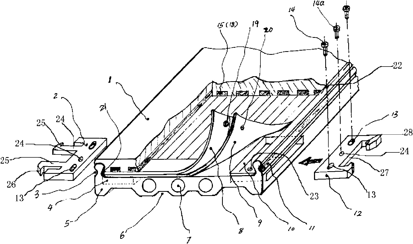
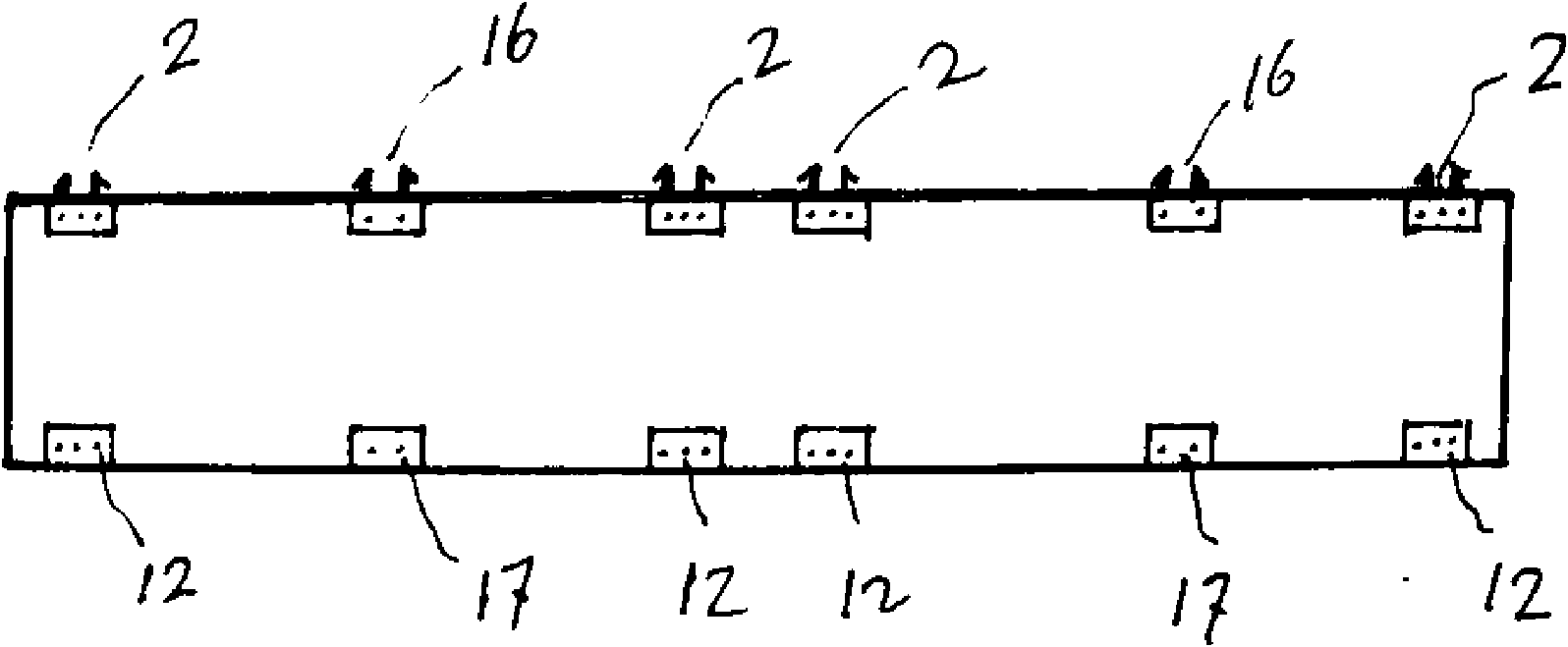
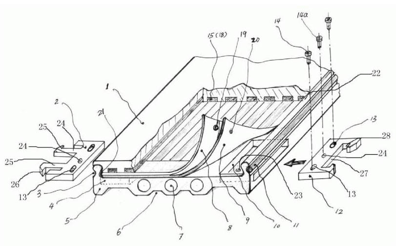
[0020] Embodiment 1: as figure 1 and figure 2 As shown, a panel 1 is arranged on a rectangular base plate 5, the base plate 5 can be formed by extrusion or injection molding of rubber-plastic material or wood-plastic material, and the panel 1 can be made of wood, bamboo veneer, MDF veneer or ceramic material; The upper edges of the left and right sides of the bottom plate 5 are respectively formed with upwardly protruding clamping strips 22, and the inside of the upper end of the clamping strips 22 forms an arc-shaped inward convex structure, thereby forming a dovetail between the two clamping strips 22 of the bottom plate 5. Groove structure, the lower edge of both sides of the panel is formed with a clip groove 21 that matches the clip 22 on the bottom plate, so that the panel snap fits on the bottom plate 5 to form a reliable assembly connection; the upper surface of the bottom plate 5 and the panel 1 correspond to An electrothermal film 8 and a heat insulating layer 9 ar...


PUM


Abstract

The invention relates to a decorative panel which is mainly laid on the ground or a wall, and belongs to the technical field of building decorative materials. The decorative panel comprises a bottom plate and a surface plate arranged on the bottom plate, wherein the bottom plate is rectangular; the left side and the right side of the bottom plate are provided with a plurality of connecting piece mounting grooves respectively; one end of each of male connecting pieces is fixedly arranged in the connecting piece mounting groove on the left side or the right side of the bottom plate through a fastener; one end of each of female connecting pieces is fixedly arranged in the connecting piece mounting groove on the right side or the left side, which is not provided with male connecting pieces, of the bottom plate through the fastener; the outer ends of the male connecting pieces can be coupled with the outer ends of the female connecting pieces of an adjacent bottom plate; the upper edges on the left side and the right side of the bottom plate are provided with clamping strips which are protruded upwards respectively; the lower edges on the two sides of the surface plate are provided with clamping strip grooves which are matched with the clamping strips on the bottom plate; the upper surface of the bottom plate is sequentially provided with an electric heating film and a heat insulating layer between the clamping strips of the left side and the right side from top to bottom correspondingly; the electric heating film is electrically connected with a power supply through the male connecting piece and the female connecting piece; the lower surface of the surface plate is provided with a plurality of open grooves in which reinforced heat conducting strips are embedded; and the reinforced heat conducting strips are made of a heat conducting material.

Description

technical field [0001] The invention relates to a veneer mainly used for laying on the ground or walls, and belongs to the technical field of building decoration materials. Background technique [0002] The traditional geothermal floor is a floor that heats the floor to a surface temperature of 1832 degrees Celsius through a heat source buried under the floor, and radiates heat evenly to the room to achieve a heating effect. This kind of floor adopts low-temperature radiant heating device, the ground temperature is high, and the compound air flows regularly. Due to the low temperature of the head, the temperature spreads from the feet to the whole body, giving people a comfortable feeling of warming the feet and cooling the head. Therefore, the geothermal floor is also in line with the theory of traditional Chinese medicine "warm feet and cool roof". Moreover, compared with the traditional heating method, geothermal heating cancels the heating pipes and radiators in the ro...

Claims


Application Information

Patent Timeline
Patent Type & Authority Applications(China)
IPC IPC(8): E04F13/076E04F13/074F24D13/02
CPCY02B30/00
Inventor 李增清
Owner 李增清
Why Eureka
Try Eureka