
Proportional flow valve controlled by pilot flow closed loop

A proportional flow valve and flow closed-loop technology, which is applied in the direction of fluid pressure actuators, servo motor components, mechanical equipment, etc., can solve the problems of large throttling loss, complex structure, and influence on control accuracy, and achieve simplified structure and simple structure , the effect of improving the accuracy

Active Publication Date: 2010-12-29
TAIYUAN UNIV OF TECH
View PDF5 Cites 20 Cited by
  • Summary
  • Abstract
  • Description
  • Claims
  • Application Information

AI Technical Summary

Problems solved by technology

[0005] The present invention improves the proportional flow valve in the prior art, and the problems to be solved are: (1) under the influence of hydraulic power, the pressure difference compensator installed on the main oil circuit has low control accuracy and large throttling loss; (2) Although the flow sensor is installed on the oil circuit, the control accuracy is improved, but the structure of the valve becomes very complicated, which increases the difficulty of valve manufacturing; (3) the cost of electronic closed-loop correction of the pressure sensor is high; (4) the existing Valvistor valve, although Only a small flow pressure differential compensator is required to compensate the differential pressure of the pilot valve, which simplifies the structure of the valve, but the flow rate of the pilot valve is still open-loop control, which affects the control accuracy of the entire valve

Method used


Image

  • Proportional flow valve controlled by pilot flow closed loop
  • Proportional flow valve controlled by pilot flow closed loop
  • Proportional flow valve controlled by pilot flow closed loop

Examples


Embodiment approach 1

[0033] The proportional flow valve for pilot flow closed-loop control of the present invention includes a proportional pilot valve 1 , a main valve 6 and a displacement sensor 13 .

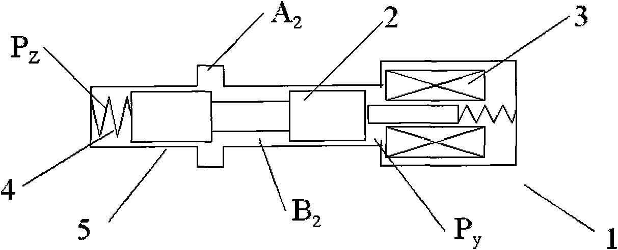
[0034] ginseng figure 1 , Proportional pilot valve 1 is composed of pilot spool 2, proportional electromagnet 3, pilot valve spring 4, pilot valve body (set) 5, pilot valve oil inlet A 2 , Pilot valve outlet B 2 , pilot valve spring oil chamber P Z and pilot valve without spring oil chamber P y constitute.

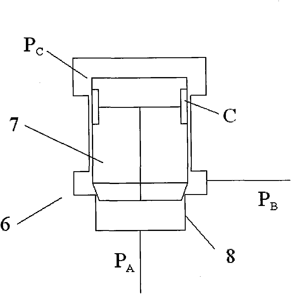
[0035] ginseng figure 2 , the main valve 6 includes the main valve core 7, the main valve sleeve 8, the main valve oil inlet P A , main valve outlet P B , the main valve control chamber P C and throttle slot C.

[0036] ginseng Figure 5 , The displacement sensor 13 is installed on the main spool 7 to detect the displacement of the main spool 7 .

[0037] A specific embodiment of the present invention is to add a flow sensor 9 composed of a two-position two-way cartridge valve.

[...

Embodiment approach 2

[0042] The second embodiment of the proportional flow valve with pilot flow closed-loop control of the present invention is the same as the first embodiment in structure and composition, and the difference is that the communication relationship is changed.

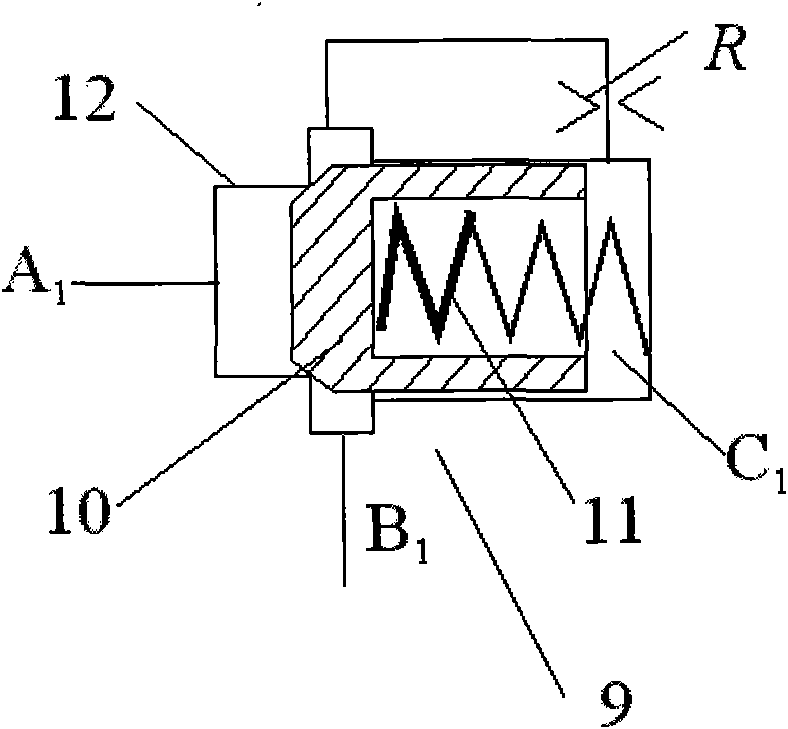
[0043] ginseng Figure 6 , its specific implementation is to control the chamber P of the main valve C and flow sensor oil inlet A 1 Connected, flow sensor outlet B 1 Simultaneously with proportional pilot valve without spring oil chamber P y , Proportional pilot valve oil inlet A 2 Connected, flow sensor outlet B 1 Through the damping hole R and the flow sensor control chamber C 1 Connected, flow sensor control chamber C 1 With pilot valve spring oil chamber P Z Connected, proportional pilot valve outlet B 2 and main valve oil outlet P B Connected, the flow sensor spool 10, the proportional pilot spool 2 and the flow sensor spring 11 are arranged coaxially. One end of the flow sensor spring 11 acts on the end fac...

Embodiment approach 3

[0046] The third embodiment of the proportional flow valve with pilot flow closed-loop control of the present invention is the same as the first embodiment in terms of structure and composition, the difference is that the communication relationship is changed.

[0047] ginseng Figure 7 , its specific implementation is to control the chamber P of the main valve C At the same time with the flow sensor inlet A 1 and pilot valve spring oil chamber P Z Connected, flow sensor outlet B 1 With proportional pilot valve inlet A 2 Connected, flow sensor outlet B 1 Through the damping hole R and the flow sensor control chamber C 1 Connected, flow sensor control chamber C 1 With pilot valve without spring oil chamber P y Connected, proportional pilot valve outlet B 2 and main valve oil outlet P B connected.

[0048] In the above embodiment, the flow sensor 9 is installed between the pilot valve and the main valve, and the oil inlet A of the flow sensor 1 The pressure acts on th...


PUM


Abstract

The invention relates to a proportional flow valve controlled by a pilot flow closed loop, which is provided with a flow sensor consisting of a two-position two-way cartridge valve. The control cavity of a main valve is communicated with the oil inlet of a pilot valve; the oil inlet of the flow sensor is communicated with the oil outlet of the pilot valve; the oil outlet of the flow sensor is simultaneously communicated with the springless oil cavity of the pilot valve and the oil outlet of the main valve; the oil outlet of the flow sensor is communicated with the control cavity of the flow sensor through a damping hole; the control cavity of the flow sensor is communicated with the spring oil cavity of the pilot valve; the valve core of the flow sensor, the valve core of the pilot valve and a flow sensor spring are coaxially arranged; and one end of the flow sensor spring acts on the core end of the pilot valve, while the other end acts on the valve core end of the flow sensor. The proportional flow valve can obtain seven technical schemes by changing communication relations. The proportional flow valve comprises an innovative idea that the flow of the pilot valve is detected by a minitype flow sensor, the flow of the pilot valve is controlled in the way of forming the closed loop and the flow of the main valve is amplified according to a Valvistor valve amplification principle. The proportional flow valve has the advantages of combining two control principle structures of flow closed loops and flow amplification and has the characteristics of simple structure, high flow control precision and high efficiency.

Description

technical field [0001] The invention belongs to a two-way proportional flow valve, more specifically, a two-position two-way proportional flow valve for continuous electro-hydraulic control of system flow. Background technique [0002] The two-way proportional flow valve is an element in the electro-hydraulic control system that continuously controls the flow supplied to the hydraulic actuator. According to the flow equation of the valve port, the flow through the valve is not only proportional to the opening area of ​​the valve port, but also influenced by the two ports of the valve port. The effect of the change in the terminal pressure difference. Therefore, the most commonly used two-way proportional flow valve to control the flow is to connect a pressure difference compensator in series at the inlet or outlet of the proportional throttle valve that controls the opening area of ​​the valve to keep the pressure difference at both ends of the proportional throttle valve co...

Claims


Application Information

Patent Timeline
IPC IPC(8): F15B13/02
Inventor 权龙李斌
Owner TAIYUAN UNIV OF TECH
Learn More