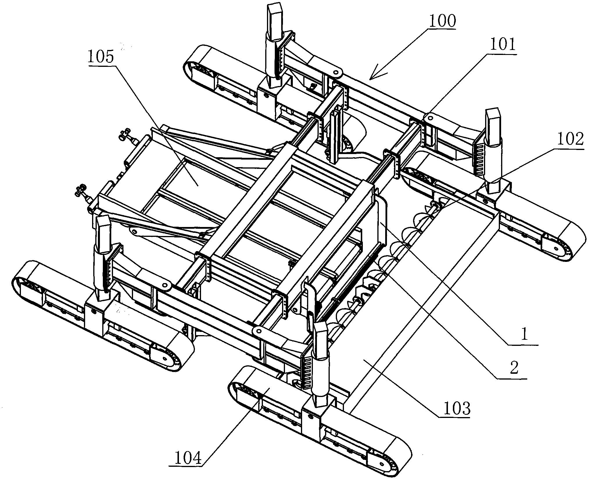
Movable asphalt spreading device and asphalt paver
A spreading device and mobile technology, applied in the directions of roads, road repair, roads, etc., can solve the problems of complex structure, affecting the quality of paving, and high cost, and achieve the effect of simple and compact structure, improving the quality of paving, and high degree of automation.
- Summary
- Abstract
- Description
- Claims
- Application Information
AI Technical Summary
Problems solved by technology
Method used
Image
Examples
Embodiment 1
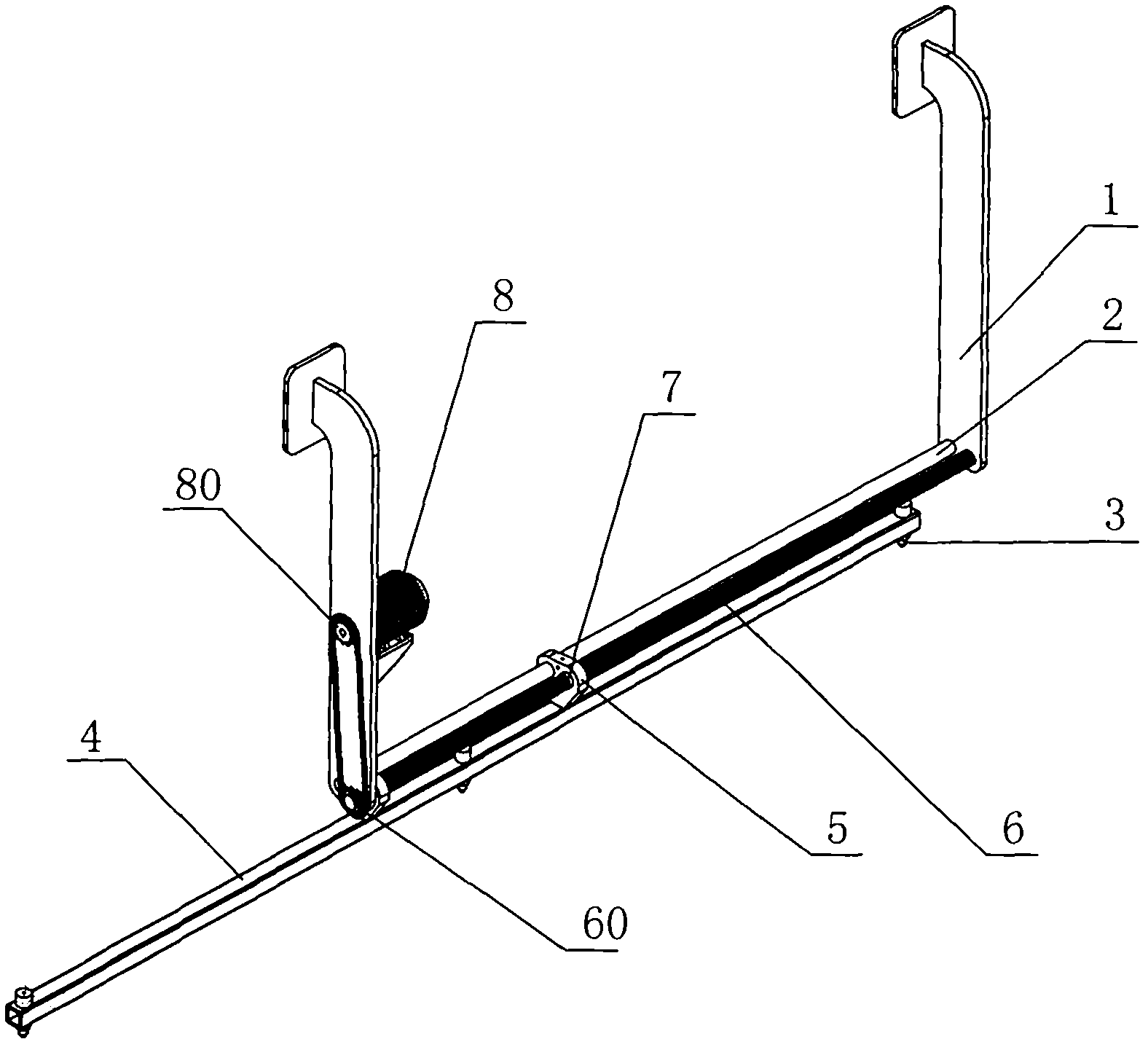
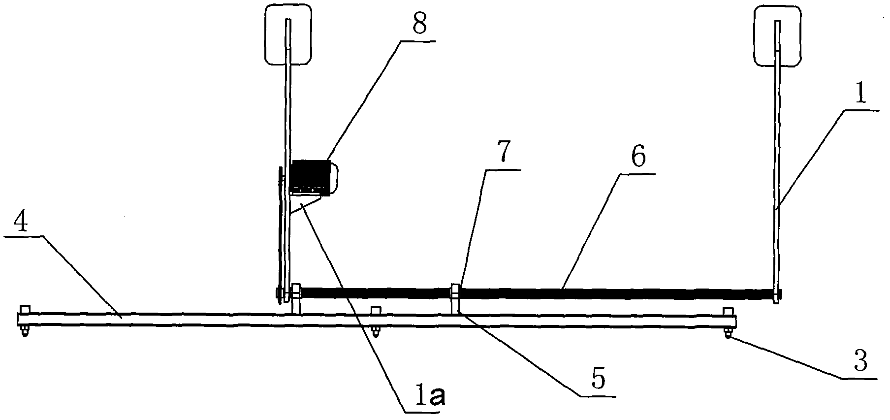
[0032] Such as figure 1 and figure 2 As shown, the mobile asphalt spreading device of this embodiment includes a guide rail mounting plate 1, a guide rail 2, an asphalt nozzle 3, a fixed square pipe 4, a fixed plate 5 and a mobile control component. For the convenience of description, the direction parallel to the guide rail 2 is defined as the transverse direction. The asphalt nozzle 3 of the present embodiment is installed on the fixed square pipe 4 at equidistant intervals, and the middle part of the fixed square pipe 4 is provided with two fixed plates 5 at intervals. Figure) is connected, is used for spraying asphalt or other emulsifiers to the ground, and the asphalt nozzle 3 of the present invention is identical in structure with the asphalt nozzle of the prior art. The fixed square tube 4 and the fixed plate 5 constitute the nozzle mounting frame of this embodiment, and the nozzle mounting frame can also adopt other forms, such as replacing the fixed plate 5 with a ...
Embodiment 2
[0035] Such as Figure 5 and Figure 6As shown, the difference between this embodiment and Embodiment 1 is that two guide rails 2 are installed between the lower parts of the two guide rail mounting plates 1, and the fixing plate 5 is installed on the two guide rails 2 and moves laterally along the guide rails 2. The fixed square tube 4 is affixed to the bottom of the fixed plate 5 and is located below the guide rail 2. A corresponding pulley 9 is installed on the opposite inner wall of the two guide rail mounting plates 1, and one of the pulleys 9 is mounted on the guide rail. The drive motor 8 on the plate 1 drives, and the steel rope 10 walks around two pulleys 9, and a certain point on the steel rope 10 is tightened and fixedly connected to the top of the fixed plate 5 with bolts. When the drive motor 8 drives the pulley 9 to rotate, the pulley 9 drives the steel rope 10 to move, and the steel rope 10 pulls the fixed plate 5 to move on the guide rail 2, so that the nozzle...
Embodiment 3
[0037] Such as Figure 7 and Figure 8 As shown, the difference between this embodiment and Embodiment 1 is that a rack 11 parallel to the guide rail 2 is installed between the two guide rail mounting plates 1, and the transverse length of the rack 11 is greater than that between the two guide rail mounting plates 1. The two ends of the rack 11 pass through the guide rail mounting plate 1, so that the rack 11 is supported on the guide rail mounting plate 1 when the rack 11 moves laterally in a direction parallel to the guide rail 2, and the rack 11 is fixed with Two fixed plates 5 arranged at intervals are fixed with a driving motor 8 through a mounting bracket 20 at the midpoint of the guide rail 2, and a driving gear 80 meshing with the rack 11 is installed on the output shaft of the driving motor 8. When the driving motor 8 drives When the driving gear 80 rotates, the rack 11 meshing with the driving gear 80 moves leftward or rightward with the rotation of the driving gear...
PUM
 Abstract
Description
Claims
Application Information
 - R&D
- Intellectual Property
- Life Sciences
- Materials
- Tech Scout
- Unparalleled Data Quality
- Higher Quality Content
- 60% Fewer Hallucinations
Browse by: Latest US Patents, China's latest patents, Technical Efficacy Thesaurus, Application Domain, Technology Topic, Popular Technical Reports.
© 2025 PatSnap. All rights reserved.Legal|Privacy policy|Modern Slavery Act Transparency Statement|Sitemap|About US| Contact US: help@patsnap.com


