Method for connecting PE (Polyethylene) winding pipes

A connection method and a technology of winding pipes, which are applied in the direction of pipeline connection layout, pipes/pipe joints/pipe fittings, mechanical equipment, etc., can solve problems such as high cost, heavy pipe weight, and poor corrosion resistance of metal flanges, and achieve convenient construction , Good anti-floating effect

Inactive Publication Date: 2011-01-05
福建亚通新材料科技股份有限公司
View PDF2 Cites 0 Cited by
  • Summary
  • Abstract
  • Description
  • Claims
  • Application Information

AI Technical Summary

Problems solved by technology

This technical solution is also relatively complicated, because the outer structure of the winding pipe has the characteristics of a spiral, and the groove fit is a thread fit. For the winding pipe with a larger diameter, the alignment is very poor, and the weight of the larger pipe is also larger. Spiral fit is quite difficult
[0005] For the connection technology of winding pipes, there are also some disadvantages such as high cost, difficult flange processing, and poor corrosion resistance of metal flanges.

Method used


Image

  • Method for connecting PE (Polyethylene) winding pipes
  • Method for connecting PE (Polyethylene) winding pipes
  • Method for connecting PE (Polyethylene) winding pipes

Examples


Embodiment Construction

[0030] specific implementation plan

[0031] The present invention will be further described below in conjunction with accompanying drawing.

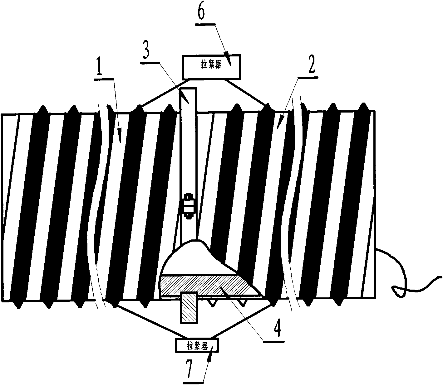
[0032] The PE winding pipe connection method of the present invention needs to be realized by using the heating ring 3 , the winding pipe inner supporting device 4 , and the tensioners 6 and 7 .

[0033] Such as figure 1 As shown, the tensioners 6 and 7 must be placed at equal intervals along the outer circumference of the PE winding pipe to ensure the balance of tension;

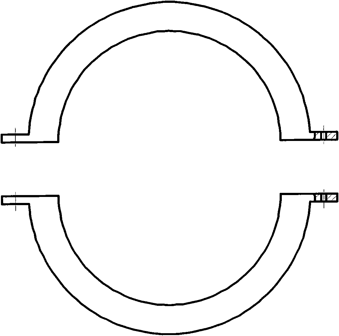
[0034] Such as image 3 As shown, the heating ring has two semicircular structures, which are easy to remove after the heat melting is completed;

[0035] Such as Figure 4 , 5 As shown in , 6 and 7, the winding tube inner support device 4 is composed of two driving sliders 11 and two driven sliders 12, and the outer walls of the driving slider 11 and the driven slider 12 are provided with a heating ring positioning groove 9, The active slider 11 and the driven...


PUM


Abstract

The invention relates to a method for connecting PE (Polyethylene) winding pipes, comprising the following steps of: placing one end of a reduced winding pipe inner-supporting device at the end of one PE winding pipe, exposing a heating ring positioning tank out of the PE winding pipe, then pushing a pull rod to support the winding pipe inner-supporting device, rotating a rotary positioning pin to make the pull rot not rotate, and fixing a heating ring on the heating ring positioning tank of the winding pipe inner-supporting device at the moment; threading a retracting and releasing rope of the winding pipe inner-supporting device through the other PE winding pipe, then inserting the PE winding pipe to the other half part of the winding pipe inner-supporting device and jacking to the heating ring; applying pulling forces to the PE winding pipes by using two tensioners placed along the outer circumference of the PE winding pipes at equal intervals, simultaneously heating the ends of the PE winding pipes contacting the heating ring, after the ends of the PE winding pipes are heated to outwards curl and reach a fusion state, loosening the tensioners, and removing the heating ring; and then immediately tensioning and butting the PE winding pipes by using the tensioners, after fully cooling, removing the tensioners, pulling the retracting and releasing rope of the winding pipe inner-supporting device to automatically retract or release the winding pipe inner-supporting device, and drawing the winding pipe inner-supporting device out by using the retracting and releasing rope. By adopting the winding pipe inner-supporting device, the method avoids the problem of inaccurate butting due to thin wall and large ellipticity of resin plates of the PE winding pipes and solves the problem that hot-melting butting with excellent connection performance cannot be adopted generally for the traditional PE winding pipes.

Description

technical field [0001] The invention relates to a pipe connection method, in particular to a PE winding pipe connection method. Background technique [0002] At present, during the construction of PE winding pipes, there are mainly several methods for connecting pipes and pipes: 1. Manual torch welding; 2. Hot-melt tape, heat shrinkable tape connection; 3. Tape connection; Among them, the welding efficiency of manual welding torch is low, and the welding effect is greatly affected by the operator's operation level; the connection of hot-melt tape and heat-shrinkable tape can only be bonded to the winding pipe with a relatively regular structure at the joint; The service life of stainless steel in the sewage environment is short, and the production cost is relatively high [0003] The invention patent with the Chinese patent application number 02152199.9 discloses a pipe connection method. In this method, a concave groove is provided on the outer wall of the joint part of on...

Claims


Application Information

Patent Timeline
Patent Type & Authority Applications(China)
IPC IPC(8): F16L47/02
Inventor 陈建福苏敏
Owner 福建亚通新材料科技股份有限公司
Why Eureka
Try Eureka