Key-press input module

A technology of input modules and buttons, applied in simulators, instruments, computer control, etc., can solve the problems of complex circuits, inconvenient use, and high cost

Inactive Publication Date: 2011-01-05
曹志才
View PDF9 Cites 1 Cited by
  • Summary
  • Abstract
  • Description
  • Claims
  • Application Information

AI Technical Summary

Problems solved by technology

Patent No. 97219874.1 The motor vehicle non-contact electric horn stabilizes the sound pressure level by adjusting the input signal strength of the power amplifier, so that the power amplifier will be in the amplified state, and the power amplifier tube will generate heat, which is easy to burn and has poor practicability
[0004] Electric horn is a necessary safety signal device on motor vehicles. With the rapid increase of the number of motor vehicles, the sound of electric horns has become one of the main sources of traffic noise. In order to reduce this noise, major and medium cities across the country , especially the bustling roads have implemented banning, although this can reduce noise, but it has brought a lot of inconvenience to drivers and pedestrians, and traffic accidents occur from time to time
At present, special devi

Method used


Image

  • Key-press input module
  • Key-press input module
  • Key-press input module

Examples


Embodiment 1

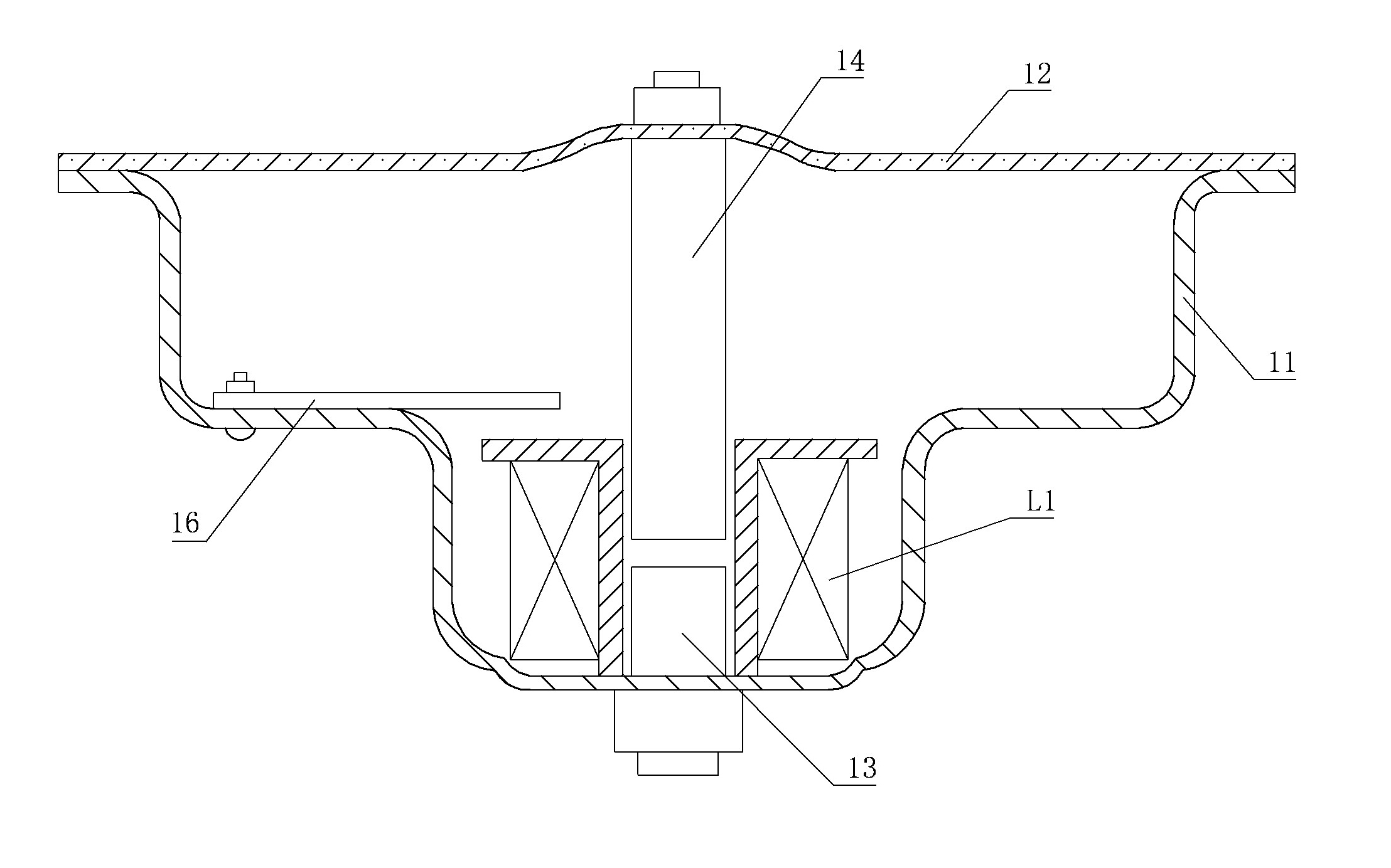
[0054] Embodiment 1: See Figure 1, Figure 5 , in the figure, the electric horn intelligent control device includes a bowl-shaped bottom shell 11, a static iron core 13, a moving iron core 14, a coil L1, a vibrating membrane 12, and a control circuit. The vibrating membrane 12 covers the top of the bowl-shaped bottom shell 11. The iron core 13 is fixed in the middle of the bowl-shaped bottom shell 11, and a moving iron core 14 is arranged above the static iron core 13. The moving iron core 14 is fixedly connected with the middle part of the vibrating membrane 12, and the coil L1 is set on the static iron core 13 and Outside the moving iron core 14, the circuit board 16 containing the control circuit is fixed on the inner wall of the bowl-shaped bottom shell 11. The control circuit contains a micro-processing module 1, a power supply module 2, a coil drive module 3, a key input module 4, and a vibrating membrane vibration The signal detection module 5, the microprocessing modul...

Embodiment 2

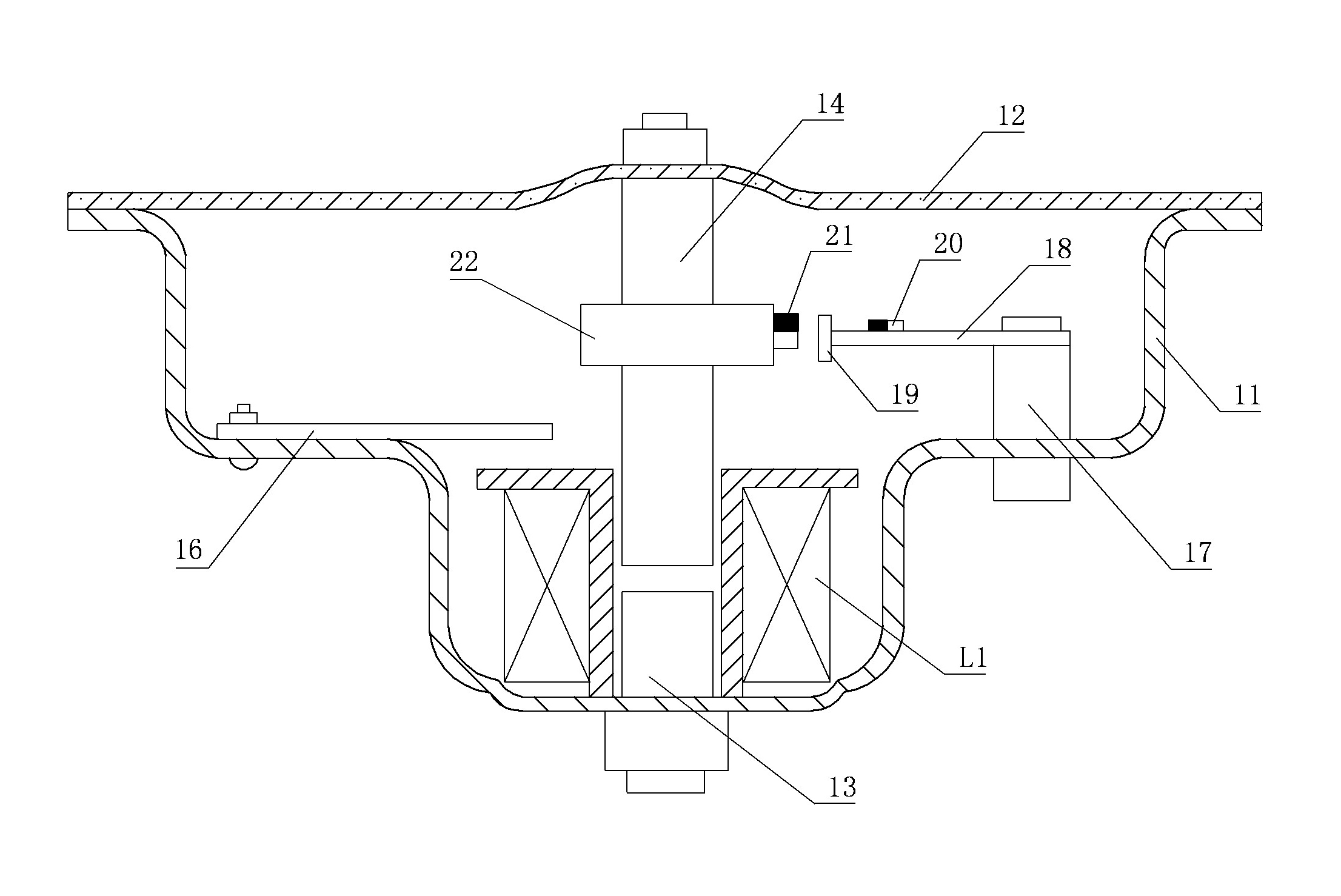
[0079] Embodiment 2: Referring to Fig. 2 and Fig. 6, the numbers in the figure are the same as those in Embodiment 1, and the representative meanings are the same, and the working process is basically the same, and the similarities will not be repeated. The difference is: the vibration signal detection of the vibrating membrane The module 5 contains a linear Hall sensor 19, the output terminal of the linear Hall sensor 19 is connected to the analog signal input terminal AN2 of the microcontroller U1, the source of the field effect transistor V2 is grounded, and a pillar 17 is vertically fixed on the inner wall of the bowl-shaped bottom case 11 , a bracket 18 is horizontally fixed on the pillar 17, a linear Hall sensor 19 is installed at one end of the bracket 18 and the linear Hall sensor 19 is close to the moving iron core 14, and the outer surface of the moving iron core 14 is provided with a fixed card 22, on which the fixed card 22 A permanent magnet 21 corresponding to the...

Embodiment 3

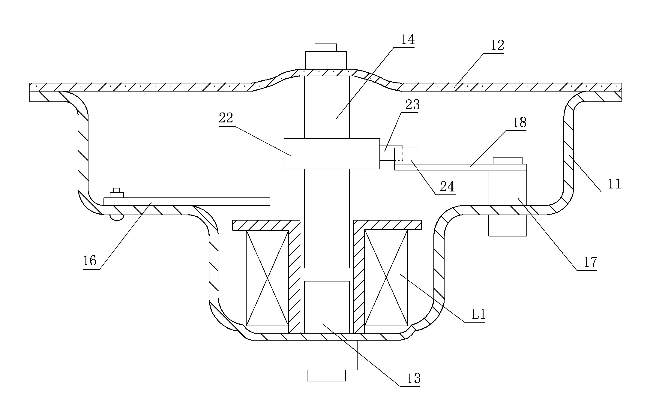
[0082] Embodiment Three: See Figure 3, Figure 7 , the numbers in the figure are the same as those in Embodiment 1, the representative meanings are the same, and the working process is basically the same. The photocoupler 24 contains emitting diode L2 and linear illuminance sensor U4, the anode of emitting diode L2 is connected to the power supply terminal of the single-chip microcomputer U1 through the resistor R10, the + terminal of the linear illuminance sensor U4 is connected to the power supply terminal of the single-chip microcomputer U1 through the resistor R11, and the linear illuminance sensor The + terminal of U4 is also connected to the analog signal input terminal AN2 of the single-chip microcomputer U1, a pillar 17 is vertically fixed on the inner wall of the bowl-shaped bottom shell 11, and a support 18 is fixed horizontally on the support 17, and a linear photocoupler 24 is installed on one end of the support 18 And the linear photocoupler 24 is close to the mov...


PUM


Abstract

The invention relates to a key-press input module which comprises a motor vehicle horn key-press, a stabilivolt tube DW2, a resistance R3 and a resistance R4, wherein one end of the motor vehicle horn key-press is connected with the power output positive end or the power output negative end of a motor vehicle battery jar, the other end of the motor vehicle horn key-press is connected with a digital signal input end IN1 of a single chip microcomputer through the resistance R3, the digital signal input end IN1 of the single chip microcomputer is also connected with a digital signal output end O1 through the resistance R4 and also the cathode of the stabilivolt tube DW2, the anode of the stabilivolt tube DW2 is in grounding, and one end of the motor vehicle horn key-press is connected with the power output positive end or the power output negative end of the motor vehicle battery jar through a single-pole double-throw switch. The invention provides the key-press input module which has the advantages of simple structure and convenient use.

Description

technical field [0001] The invention relates to a key input module. Background technique [0002] At present, the driving frequency of electric horns of motor vehicles is fixed before leaving the factory, and the natural frequency of electric horns will change due to changes in environmental conditions during use (for example: changes in temperature between winter and summer, air pressure between plains and plateaus) Changes, etc.) and changes in the mechanical properties of the electric horn can cause its change. Since the resonant peak of the electric horn diaphragm is very sharp, if the driving frequency cannot be adjusted in time, it may cause a sharp drop in the sound pressure level of the electric horn , or even be scrapped, which will affect the prompting effect and increase the energy consumption. For example: Patent No. 98807769.8 The method and device for frequency stabilization of electric horns, the driving frequency is solidified in the program before leaving t...

Claims


Application Information

Patent Timeline
IPC IPC(8): G05B19/042
Inventor 曹志才
Owner 曹志才
Why Eureka
Try Eureka